Saw element and saw device

a technology of surface acoustic wave and saw element, which is applied in the direction of piezoelectric/electrostrictive/magnetostrictive devices, electrical apparatus, impedence networks, etc., can solve the problems of reducing the film thickness, affecting the power consumption of mobile communication terminal equipment including the saw element, and preventing the insertion loss of the saw element. , to achieve the effect of easily changing the attenuation characteristics of the element and preventing the loss

Inactive Publication Date: 2006-10-03
SNAPTRACK
View PDF24 Cites 35 Cited by
  • Summary
  • Abstract
  • Description
  • Claims
  • Application Information

AI Technical Summary

Benefits of technology

[0011]It is therefore an object of the present invention to provide an SAW element and an SAW device each of which is not only capable of preventing an insertion loss thereof from being deteriorated but also capable of readily changing attenuation characteristics thereof.

Problems solved by technology

Herein, the insertion loss influences power consumption of the mobile communication terminal equipment including the SAW element.
Such an influence on the frequency characteristic due to the coupling is a serious problem regarding characteristics of the SAW device itself.
The insertion loss influences power consumption of the mobile communication terminal equipment.
Such reduction of the film thickness inevitably makes an area of section of a conductor pattern be small.
Further, the amount of attenuation outside the pass band frequency cannot be obtained sufficiently.
Thus, characteristics of the SAW element are deteriorated.

Method used


Image

  • Saw element and saw device
  • Saw element and saw device
  • Saw element and saw device

Examples


third embodiment

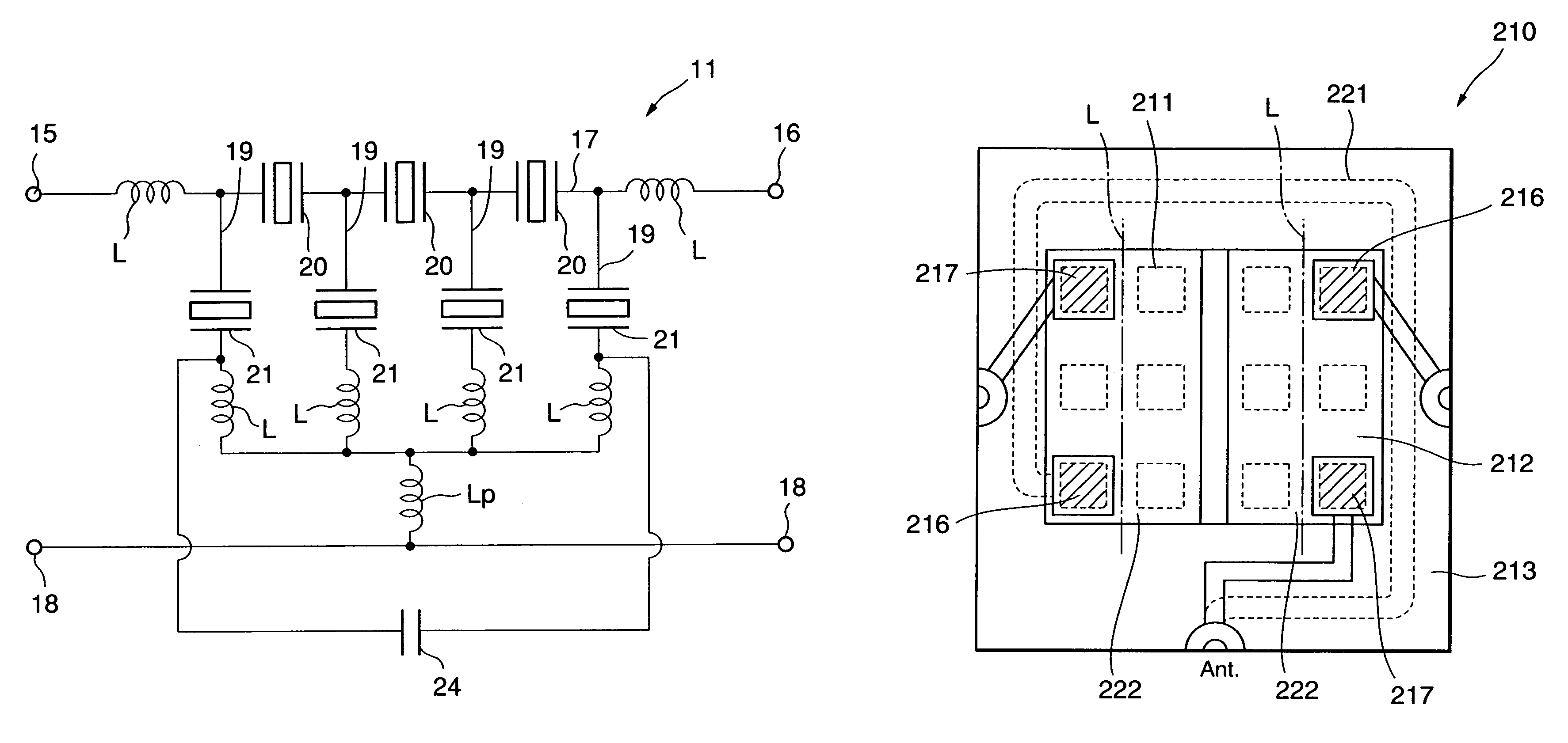
[0123]As illustrated in FIG. 6, in the SAW element 11 a serial arm (first wiring portion) 17 is formed between an input terminal 15 and an output terminal 16. Further, a plurality of (four) parallel arms (second wiring portions) 19 are connected between the serial arm 17 and reference potential terminals 18. Accordingly, a ladder-type circuit is constituted by the serial arm 17 and the parallel arms 19.

[0124]In the serial arm 17, two first SAW resonators 21 which have a predetermined resonant frequency and the anti-resonant frequency are located in serial to each other. Further, a fourth SAW resonator 26 is located between the two first SAW resonators 21 adjacent to each other. Further, the parallel arms 19 are formed between an input terminal 15 and the first SAW resonator 21 of the nearest position to the input terminal 15, between an output terminal 16 and the first SAW resonator 21 of the nearest position to the output terminal 16, and between the first SAW resonators 21 adjace...

fifth embodiment

[0138]In order to solve the problem, the following embodiment of the present invention is provided. FIG. 10 is a sectional view for showing an SAW device according to the present invention. FIG. 11 is a graph for showing a frequency characteristic of the SAW device illustrated in FIG. 10. FIG. 12 is a schematic view for showing a conductor pattern formed in a reception filter of the SAW device illustrated in FIG. 10. FIG. 13 is a schematic view for showing a conductor pattern formed in a transmission filter of the SAW device illustrated in FIG. 10. FIG. 14 is a plan view for showing a mounting substrate of the SAW device illustrated in FIG. 10, in which the reception and the transmission filters are mounted. FIG. 15 is a block diagram for showing a constitution illustrated in FIG. 14. FIG. 16 is an explanation view for showing an example of location of electrodes of the reception and the transmission filters in the SAW device illustrated in FIG. 10. FIG. 17 is an explanation view fo...


PUM


Abstract

The SAW element 11 comprises a serial arm 17 formed between an input terminal 15 and an output terminal 16, two serial arm side SAW resonators 20 located in the serial arm 17, at least three parallel arms 19 connected between the serial arm 17 and a reference potential terminal 18, and parallel arm side SAW resonator 21 located in the parallel arms 19, respectively. Each of these parallel arm side SAW resonators 21 has an anti-resonant frequency corresponding with the predetermined resonant frequency of each serial arm side SAW resonator 20. Further, at least one parallel arm side SAW resonator 21 has a resonant frequency different from those of the other parallel arm side SAW resonators 21. Thereby, not only insertion loss can be prevented from being deteriorated but also an attenuation characteristic of the SAW element 11 can be readily varied.

Description

[0001]The present Application is a Divisional Application of U.S. patent application Ser. No. 10 / 253,988, filed on Sep. 25, 2002, now abandoned.BACKGROUND OF THE INVENTION[0002]The present invention relates to an SAW (Surface Acoustic Wave) element which is composed of a plurality of SAW resonators, and an SAW device in which the SAW element is mounted, in particular to a technique effectively applicable to the SAW element of which a ladder-type circuit is constituted by these SAW resonators. Further, the present invention is also applied to a dual-type filter and a branching filter each of which is using a plurality of SAW elements. Furthermore, the present invention also relates to a technique effectively applicable in particular to reduction of coupling between a plurality of SAW elements.[0003]In recent years, a mobile communication terminal equipment, such as a portable telephone, and the like has been rapidly progressed. From the viewpoint of convenience of portability or hand...

Claims


Application Information

Patent Timeline
Patent Type & Authority Patents(United States)
IPC IPC(8): H03H9/64H03H9/72H03H3/08
CPCH03H9/0576H03H9/1071H03H9/6483H03H9/72H03H9/725H03H3/08H03H2009/0019
Inventor INOUE, KENJI
Owner SNAPTRACK
Why Eureka
Try Eureka