
Alternative energy system control method and apparatus

Active Publication Date: 2006-10-03
SQUARE D CO
View PDF12 Cites 69 Cited by
  • Summary
  • Abstract
  • Description
  • Claims
  • Application Information

AI Technical Summary

Benefits of technology

"The present invention is a method and apparatus for controlling a multi-variable system using a common control component. The control monitoring and selection logic selects the control variable to be regulated based on desired control modes and the states of monitored variables. The apparatus includes a common control circuit with appropriate control response, gains, delays, filtering, etc., in consideration of the control variable to be regulated. The apparatus can selectively switch regulation control over to another control variable if it exceeds its allowed value. The invention can be implemented as computer program instructions and an alternative energy system control apparatus. The technical effects of the invention include improved control accuracy and efficiency, as well as improved system reliability and stability."

Problems solved by technology

Controlling such systems based on a plurality of different, potentially conflicting, system variables presents a significant control challenge, particularly where the systems operate in and switch between a variety of modes, such as stand alone, grid-connected, etc.

Method used


Image

  • Alternative energy system control method and apparatus
  • Alternative energy system control method and apparatus
  • Alternative energy system control method and apparatus

Examples


Embodiment Construction

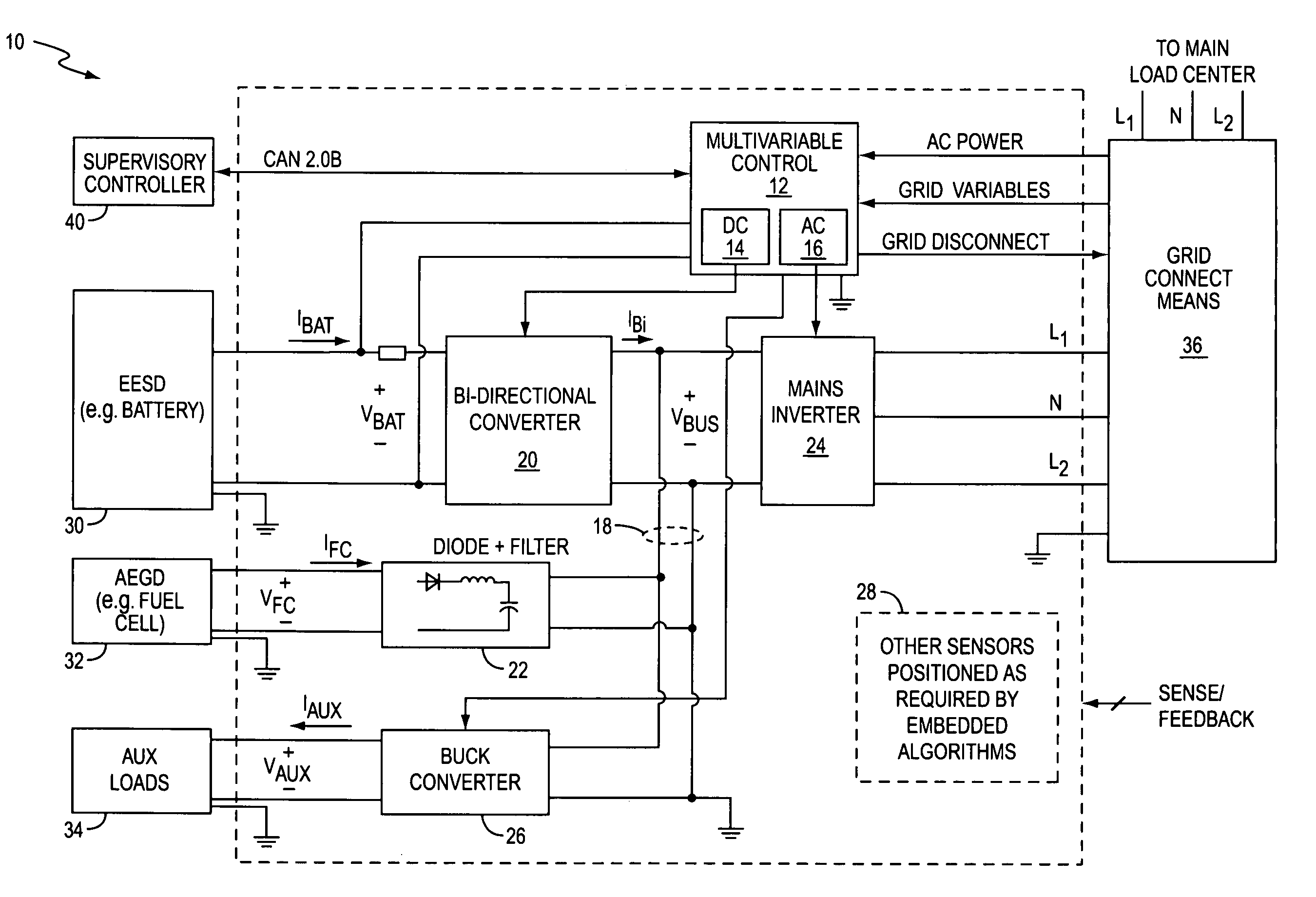
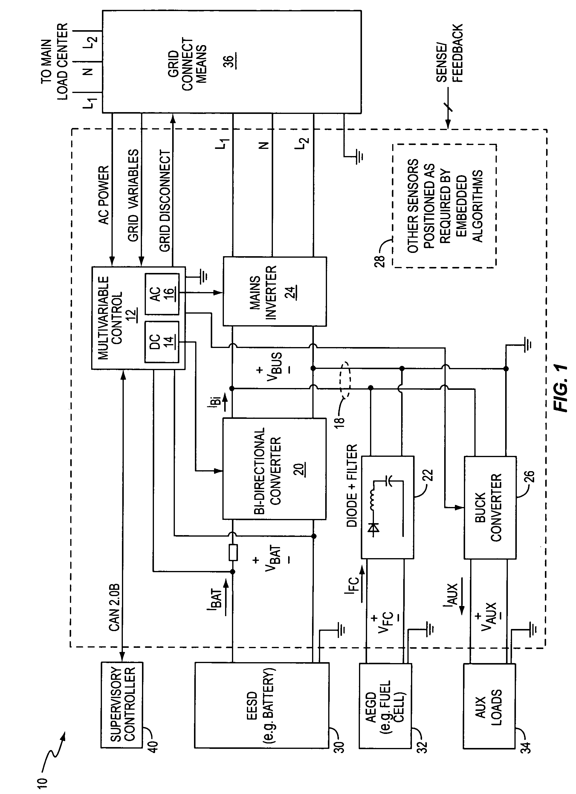
[0019]FIG. 1 illustrates an exemplary multivariable control system 10 that is configured for operation in an alternative energy system. System 10 comprises a multivariable controller 12, that comprises a “dc control”14 and an “ac control”16, along with higher level logic controls, a shared (common) dc bus 18, a bi-directional converter 20, a reverse blocking circuit 22, a mains inverter 24, a converter circuit 26, and one or more sensors 28 to support control operations of the system 10. In its alternative energy system configuration, system 10 is associated with battery (or batteries) 30, a fuel cell 32, one or more auxiliary loads 34, grid connect means 36, and a supervisory controller 40. Grid connect means 36 can comprise contactors or the like. Also, although they can comprise other or additional items, the auxiliary loads 34 typically represent elements that provide mechanical support to the fuel cell 32.

[0020]It should be understood that system 10 can be associated with essen...


PUM


Abstract

A multivariable control system provides regulation for a plurality of control variables of interest based on selecting a particular one of the variables for regulation relative to a corresponding setpoint, while continuing to monitor the other variables and switching regulation control over to another one of the variables as needed to maintain all of them within their allowed ranges. The system includes one or more PID regulators that tune themselves for the particular variables selected for regulation control. In an exemplary embodiment, the control system is configured for controlling an alternative energy system, wherein it includes one or more power flow devices that control power flow between electrical energy storage devices (EESDs) and a common dc bus and / or power flow between the dc bus and an external ac electrical system.

Description

BACKGROUND OF THE INVENTION[0001]The present invention generally relates to alternative energy systems, and particularly relates to the control of such systems.[0002]Alternative energy systems represent an increasingly viable alternative to or supplement to conventional utility grid power. For example, advancements in power generation and control technologies have increased the power density and reliability of fuel cell based generation systems such that those types of systems are increasingly realistic for use in providing localized power for residences and small business, and even in providing opportunities for cogeneration wherein a grid-connected alternative energy system injects a portion of its output power into the utility grid.[0003]Typically, such systems convert dc power from a fuel cell (or other local source) into ac power using a power inverter. Further, such systems typically include one or more batteries to provide backup power, and, at least on a temporary basis, to ...

Claims


Application Information

Patent Timeline
Patent Type & Authority Patents(United States)
IPC IPC(8): G05B13/02G05B11/32G05B11/42
CPCG05B11/32G05B11/42
Inventor KOCHER, MARK JOHNCARSON, GERALD BENJAMIN
Owner SQUARE D CO
Learn More