Process and system for designing molds and dies

Inactive Publication Date: 2006-10-03
CORTECHSOFT
View PDF11 Cites 18 Cited by
  • Summary
  • Abstract
  • Description
  • Claims
  • Application Information

AI Technical Summary

Problems solved by technology

Molds and dies are complex mechanisms for forming uniquely shaped parts in a plastic molding, die casting or metal stamping process.
The use of predefined parts does not account f

Method used


Image

  • Process and system for designing molds and dies
  • Process and system for designing molds and dies
  • Process and system for designing molds and dies

Examples


Embodiment Construction

[0014]An embodiment of this invention is a process and system of designing a tooling assembly such as a plastic injection mold or die where each part is designed in accordance with predetermined criteria and in consideration of interrelationships with other components within the tooling assembly.

[0015]This disclosure details as an example the process steps used to design a plastic injection mold. It should be understood that although the specific example of the design of a plastic injection mold is discussed, it is within the contemplation of this invention to apply this process to the design of molds, dies and other complex tooling assemblies.

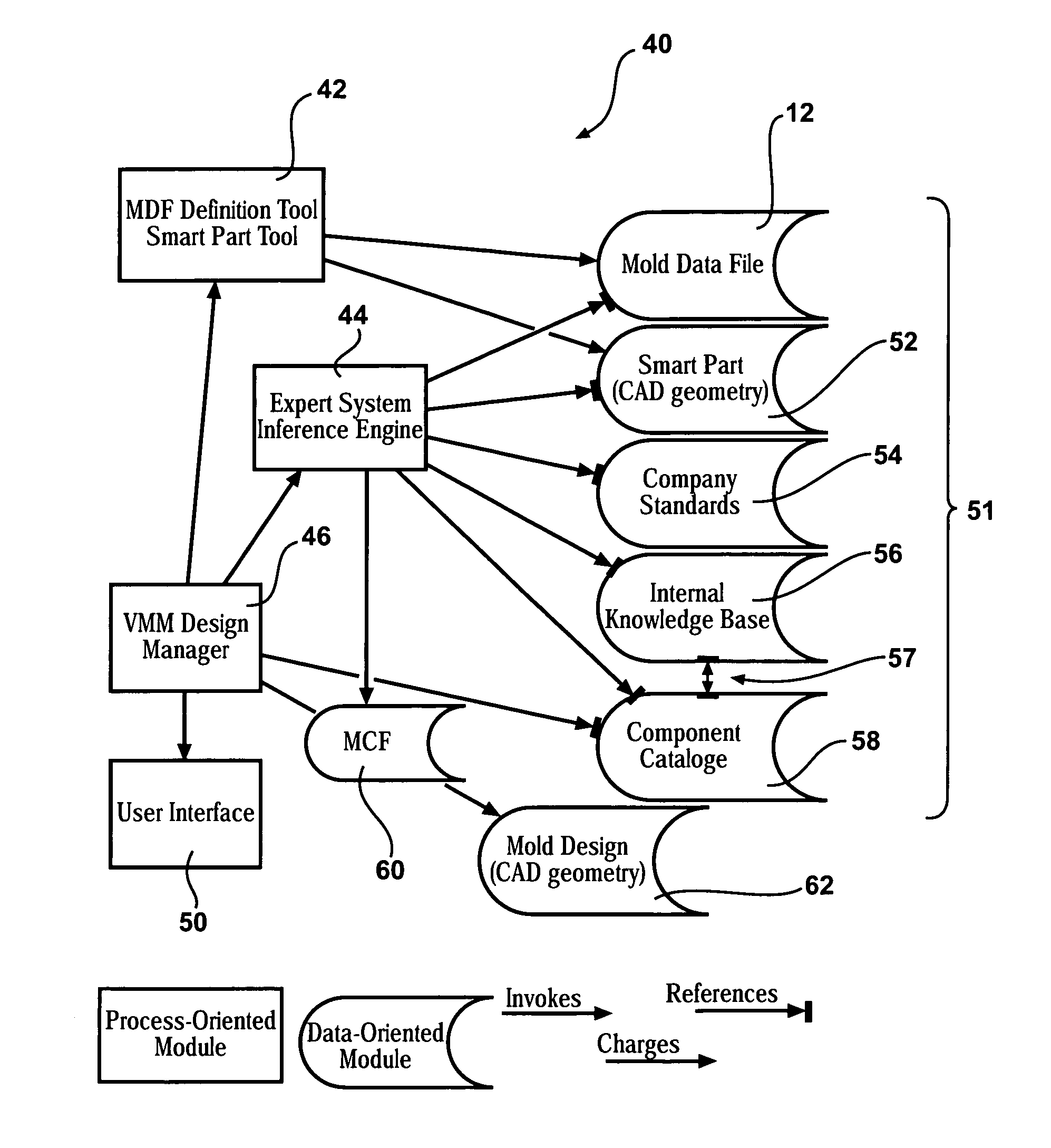
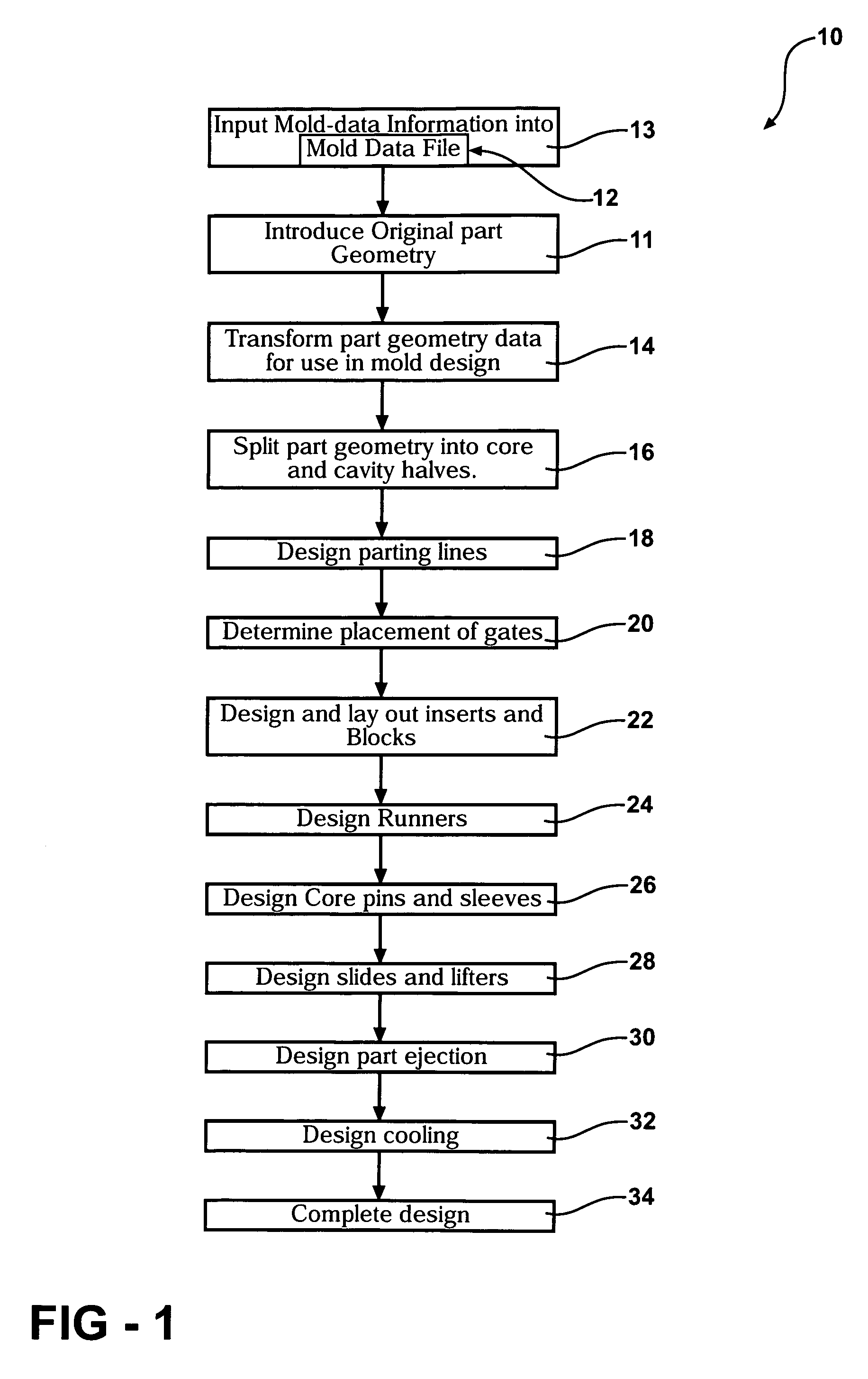
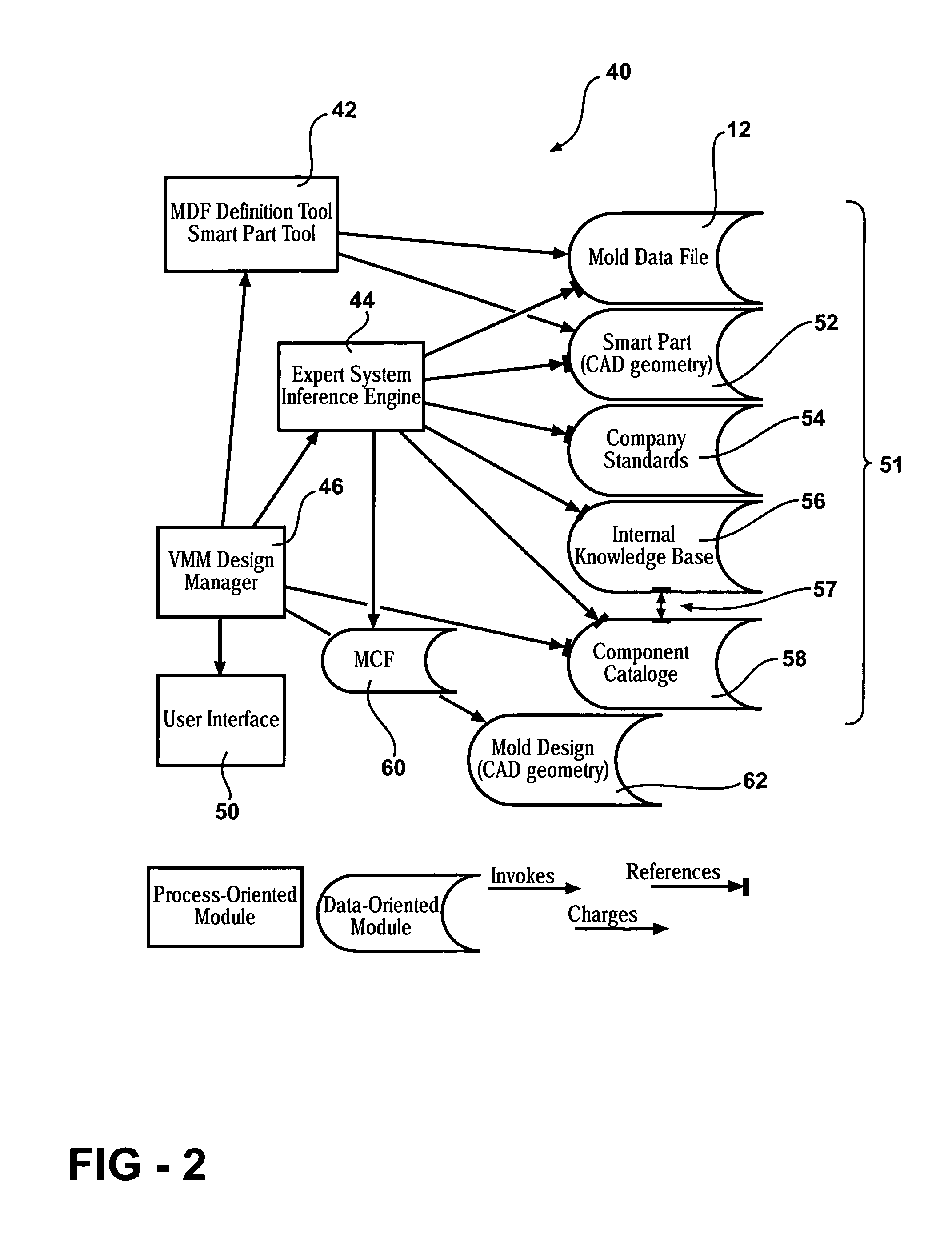
[0016]The process of designing a mold utilizing part geometry data according to a data file according to interrelationships between all parts of the mold is schematically shown at 10 in FIG. 1. This includes the initial step of inputting mold specification data into a Mold Data File 12 indicated at 13. Mold specification data is transformed in...


PUM

PropertyMeasurementUnit
Configurationaaaaaaaaaa

Abstract

A system and method for designing a tooling assembly automatically validates and maintains relationships between components in view of predefined requirements, preferences, and best design practices. The process is performed as part of a program performed by a computer system. A database containing information relevant to the design of the tooling assembly such as design standards, customer requirements and other desired attributes of the completed tooling assembly is used to define a set of requirements for each component. The specific part configuration for each component is then stored in a Master Control File for validation with respect to other components within the tooling assembly to maintain interrelationships between each component within the tooling assembly.

Description

[0001]This application claims priority to U.S. provisional patent application Ser. No. 60 / 388,914 filed on Jun. 14, 2002.BACKGROUND OF THE INVENTION[0002]This invention relates to a process and system for designing a tooling assembly such as a mold or die, and specifically to a tooling assembly design process and system accommodating and validating interrelationships between components.[0003]Molds and dies are complex mechanisms for forming uniquely shaped parts in a plastic molding, die casting or metal stamping process. Each mold or die is unique to the specific part fabricated and therefore requires a unique design. A conventional design begins with the desired shape of the finished part and proceeds with the design of a cavity to properly form the part. The design progresses by designing runner systems to carry material to the mold cavity, cooling systems to control cooling of the part after injection of molten material in addition to support, opening and part ejection mechanism...

Claims


Application Information

Patent Timeline
IPC IPC(8): G06F19/00G05B19/18G05B19/4093G06F9/44
CPCG05B19/188G05B19/40938G05B2219/35044G05B2219/36284Y02P90/02
Inventor MATEAU, JOHNBALJEU, ALAN
Owner CORTECHSOFT
Why Eureka
Try Eureka