Oil-scraper piston ring and a method for producing an oil-scraper piston ring

a technology of oil-scraper and piston ring, which is applied in the direction of braking systems, closures, packaging, etc., can solve the problems of unavoidable formation of different running surfaces in height and radial expansion in the region of running rails, inability to provide coatings for tapered running surfaces, and inability to achieve optimal oil consumption. , to achieve the effect of reducing oil consumption

Inactive Publication Date: 2006-10-10
FEDERAL MOGUL BURSCHEID
View PDF21 Cites 24 Cited by
  • Summary
  • Abstract
  • Description
  • Claims
  • Application Information

AI Technical Summary

Benefits of technology

[0004]It is the object of the invention to devise a method for producing a piston oil control ring, which ensures that the running rail or rails provided are such that both running rails have essentially the same running surface heights and radial extensions relative to the corresponding cylinder wall. In addition, the piston oil control ring provided should result in minimized oil consumption for the respective internal combustion engine, particularly in the running-in state, while simultaneously having a long service life.
[0010]The production method according to the invention results in a piston oil control ring design with a uniformly high running surface in the region of the running rail or running rails, as seen across the circumference, which running rails—when using piston oil control rings with two or more running rails—are designed with identical radial extension. Consequently, the running surfaces of all running rails are pressed with essentially the same force against the corresponding cylinder wall. This measure leads to a reduction in the oil consumption for the respective internal combustion engine, particularly during the running-in phase.

Problems solved by technology

The problem until now was that coatings for these tapered running surfaces could not be provided with a uniform lapping along the complete ring circumference and on both running rails with the same radial dimensions or defined only in the upper region to ensure that a reduction in the oil consumption is a given during the running-in behavior.
However, one disadvantage to be mentioned here is that when arranging two running rails and coating these with a wear-resistant coating, different running surfaces with respect to height and radial expansion are unavoidably formed in the region of the running rails during the subsequent lapping operation.
In addition to differences in the wear behavior of the two running rails or the associated running surfaces, this also results in a non-optimum oil consumption, particularly during the running-in behavior of the piston oil control ring.

Method used


Image

  • Oil-scraper piston ring and a method for producing an oil-scraper piston ring
  • Oil-scraper piston ring and a method for producing an oil-scraper piston ring

Examples


Embodiment Construction

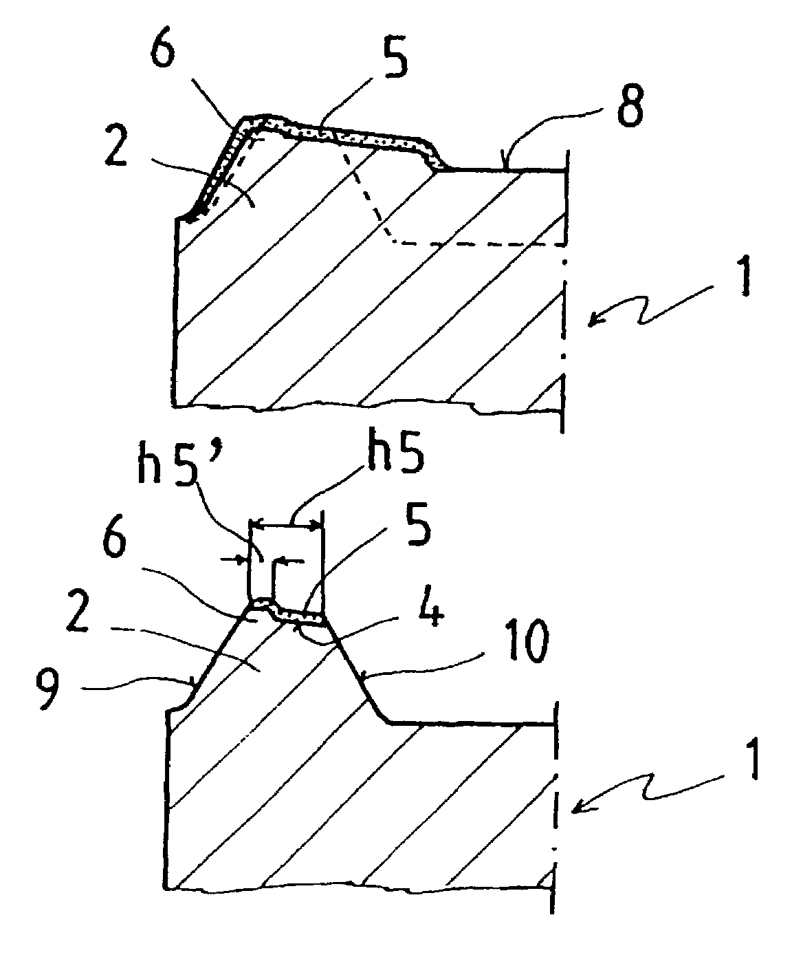
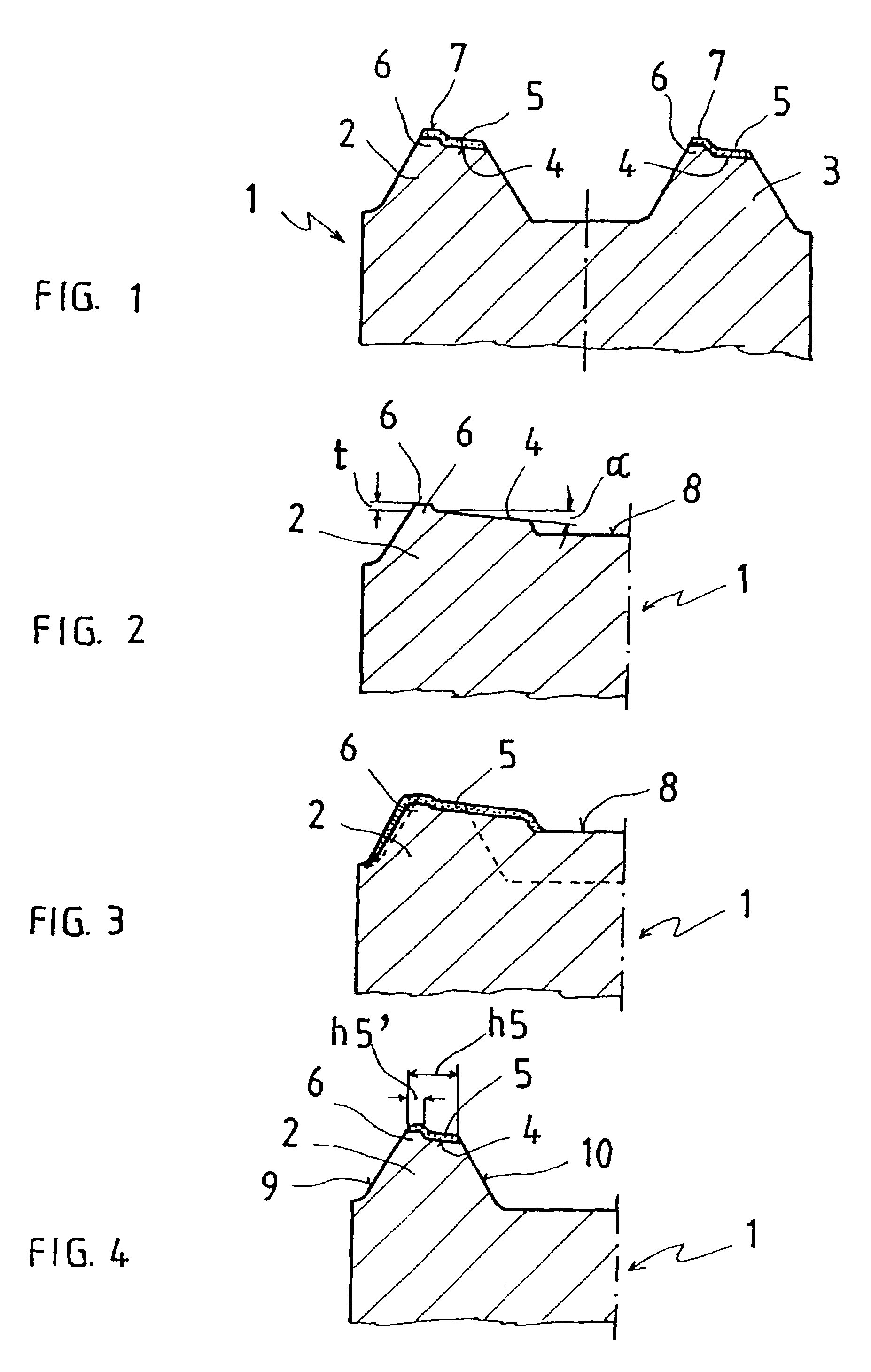
[0014]FIG. 1 shows a schematic representation of the piston oil control ring 1 according to the invention, which is provided with two running rails 2, 3. The outer circumferential surface 4 of the piston oil control ring 1 that is not provided with a wear-resistant layer has a tapered design. Before depositing the wear-resistant layer 5, which for this example is a chrome layer, the running rails 2, 3 of the piston oil control ring are provided with radially outward extending elevations 6 along the circumference (forming a step in each running rail), so that following the coating operation, the chrome layer 5 is also provided in this region 6. The elevations 6 for this example have a cylindrical design, which also applies to the wear-resistant layer 5 in this region. With a mechanical machining operation, uniformly high running surfaces 7 are formed in circumferential direction in the region of these radial elevations 6.

[0015]FIGS. 2 to 4 show different production stages for the pis...


PUM

PropertyMeasurementUnit
circumferenceaaaaaaaaaa
cylindrical outer circumferenceaaaaaaaaaa
heightaaaaaaaaaa

Abstract

A piston oil control ring with at least one tapered running rail, provided with a wear-resistant coating, characterized in that a radial elevation with predetermined radial height and width, which is provided with the wear-resistant coating, is provided in the region of the tapered ring plane for the running rail.

Description

BACKGROUND OF THE INVENTION[0001]The invention relates to a method for producing a piston oil control ring.[0002]Producing non-coated piston oil control rings with tapered running rails is generally known. The problem until now was that coatings for these tapered running surfaces could not be provided with a uniform lapping along the complete ring circumference and on both running rails with the same radial dimensions or defined only in the upper region to ensure that a reduction in the oil consumption is a given during the running-in behavior.[0003]Reference DE-A 42 36 641 discloses a piston oil control ring for internal combustion engines, which operates jointly with a coil wire spring that pushes its two running rails against the corresponding cylinder wall. The running rails in this case have a tapered design and are coated with a wear-resistant chrome layer. However, one disadvantage to be mentioned here is that when arranging two running rails and coating these with a wear-res...

Claims


Application Information

Patent Timeline
Patent Type & Authority Patents(United States)
IPC IPC(8): B21K1/14F02F5/00F16J9/20F16J9/26
CPCF16J9/206Y10T29/49274Y10T29/49297F16J15/062F16J9/22Y10S277/909
Inventor PREYER, KARLFRIED
Owner FEDERAL MOGUL BURSCHEID
Why Eureka
Try Eureka