Liquid level detecting apparatus

a detection apparatus and liquid level technology, applied in the direction of instruments, specific gravity measurement, machines/engines, etc., can solve the problems of unstable indicated value of fuel indicators, difficult to keep the positional relationship of both constituents highly accurate, and difficult to detect liquid level at a high accuracy. achieve the effect of accurately and stably detecting the height of a liquid surfa

Active Publication Date: 2006-10-10
DENSO CORP
View PDF9 Cites 13 Cited by
  • Summary
  • Abstract
  • Description
  • Claims
  • Application Information

AI Technical Summary

Benefits of technology

[0013]An object of the present invention is to provide a liquid level detecting apparatus which can detect the height of a liquid surface accurately and stably.

Problems solved by technology

Accordingly, it becomes difficult to detect the liquid level at a high accuracy.
Then, the problem occurs that the indicated value of a fuel indicator becomes unstable.
In the prior-art liquid level detecting apparatus stated above, however, the reflector is a component separate from the ultrasonic sensor, and it becomes difficult to keep the positional relationship of both the constituents highly accurate, because of the construction in which these constituents are fixed to the container.
Therefore, when the accuracy of the positional relationship between both the constituents lowers, the ultrasonic velocity in the liquid cannot be detected at a high accuracy, making it impossible to accurately detect the liquid level position.

Method used


Image

  • Liquid level detecting apparatus
  • Liquid level detecting apparatus
  • Liquid level detecting apparatus

Examples


first embodiment

(First Embodiment)

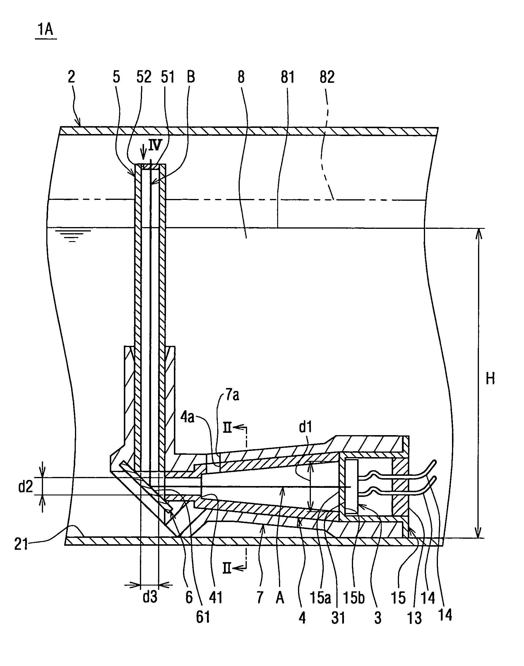
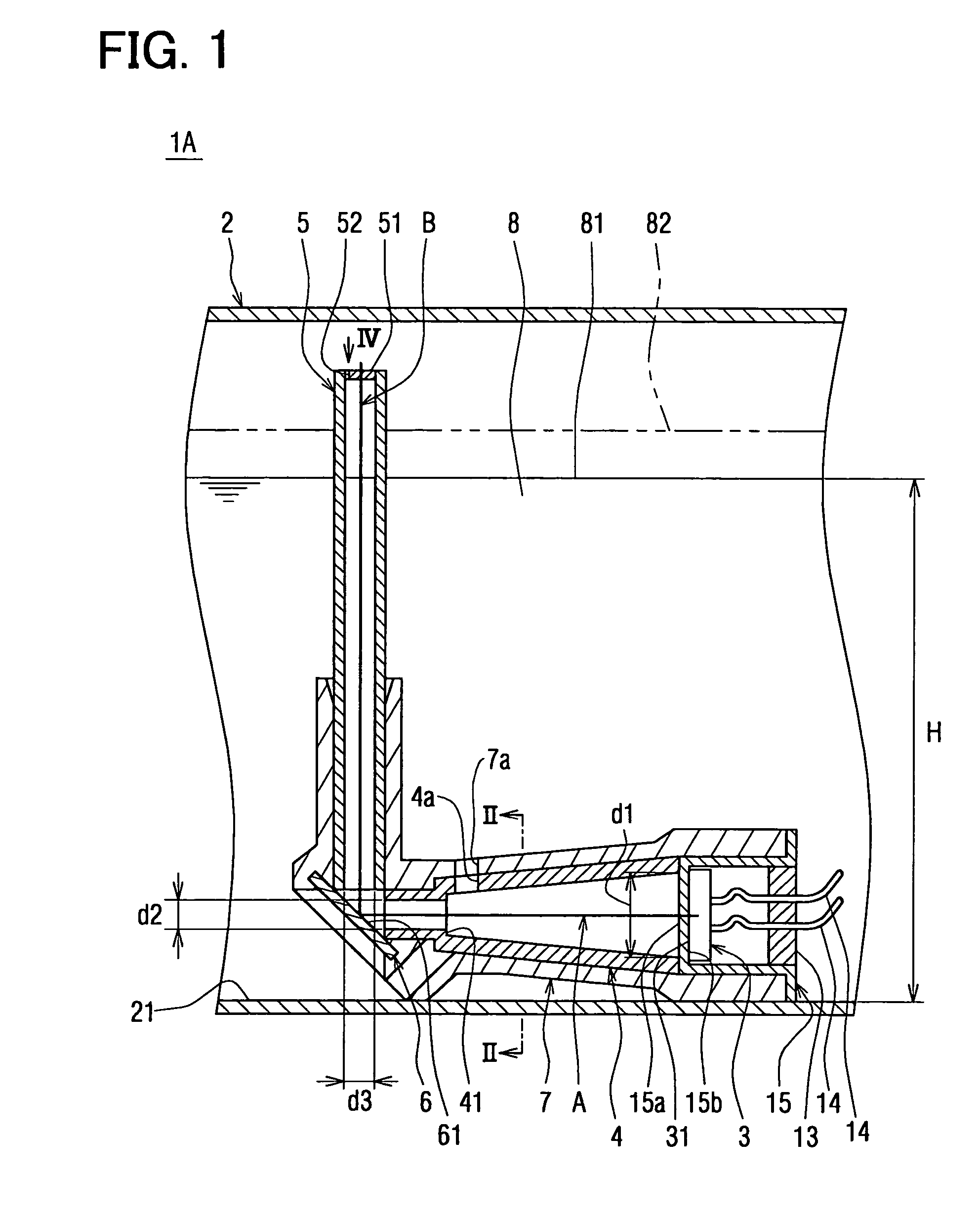
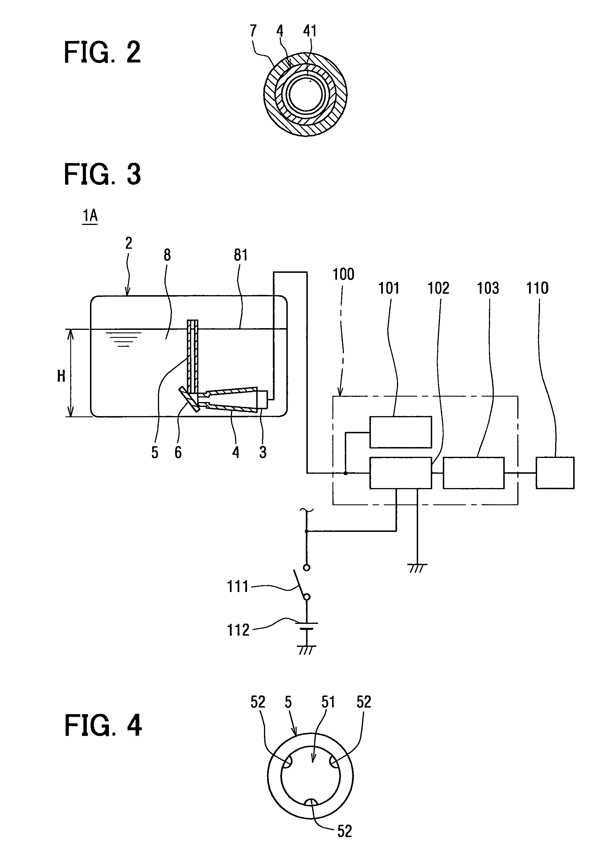
[0051]As shown in FIG. 1, a fuel liquid level detecting apparatus 1A includes a fuel tank 2, an ultrasonic sensor 3, a guide pipe (first cylinder) 4, a reflector plate 6, and a guide pipe (second cylinder) 5. Herein, the ultrasonic sensor 3, guide pipe 4, reflector plate 6 and guide pipe 5 are unitarily accommodated and held in a body 7, and they are attached to the bottom surface 21 of the fuel tank 2 through the body 7 as shown in FIG. 1.

[0052]The ultrasonic sensor 3 is installed on one end side of the guide pipe 4 in a state where the ultrasonic generation surface 31 thereof for generating an ultrasonic wave opposes to the interior of the guide pipe 4. That is, the ultrasonic sensor 3 is fixed to a bracket 15, and the bracket 15 is fitted in the body 7.

[0053]The ultrasonic sensor 3 is formed from a substance having a piezoelectric effect, for example, PZT (lead titanate zirconate). The ultrasonic sensor 3 has lead wires 14 for connection to an external electric ...

second embodiment

(Second Embodiment)

[0090]As shown in FIG. 5, a fuel liquid level detecting apparatus 1B in a second embodiment is such that the guide pipe (first cylinder) 4 of the fuel liquid level detecting apparatus 1A in the first embodiment is altered into a shape to be stated later, and that a baffle plate 9 is installed in the guide pipe (second cylinder) 5 instead of the dashboard 51. Besides, the bracket 15 of the fuel liquid level detecting apparatus 1B is such that the bracket 15 and the plug 13 fitted therein in the fuel liquid level detecting apparatus 1A of the first embodiment, are unitarily formed. The other constituents of the fuel liquid level detecting apparatus 1B are constructed similarly to the corresponding constituents of the fuel liquid level detecting apparatus 1A, respectively.

[0091]The guide pipe 4 is formed in the shape of a cylinder of uniform sectional shape from an aluminum die casting alloy. An ultrasonic sensor 3 is attached to one end side of the guide pipe 4 (rig...

modification to second embodiment

(Modification to Second Embodiment)

[0120]In the modification of the baffle plate 9 as shown in FIG. 8, the baffle plate 9 is formed to be square. In this case, it is also allowed to employ a polygon different from the square, which has three or more apices.

[0121]In the other modification of the baffle plate 9 as shown in FIG. 9, the baffle plate 9 is in the shape of a circle, the two circumferential parts of which are cut away.

[0122]By the way, in the fuel liquid level detecting apparatus 1B, the guide pipe 4 is formed from the aluminum die casting alloy, while the guide pipe 5 is formed of the stainless steel pipe. However, the guide pipes 4 and 5 need not be restricted to these metal materials, but they may well be formed in a combination of other substances. Alternatively, they may well be formed from an identical substance. Further, the guide pipes 4 and 5 may well be formed as a unitary component.

[0123]Besides, in the fuel liquid level detecting apparatus 1B, the baffle plate 9...


PUM


Abstract

A guide pipe is formed from a metal material, and its internal cross section has a circular shape whose diametric dimension gradually becomes smaller with a distance from an ultrasonic sensor. That is, the guide pipe is formed so that a route for transmitting an ultrasonic wave generated from the ultrasonic sensor may be tapered from this ultrasonic sensor toward a reflector plate. Thus, the acoustic pressure level of the ultrasonic wave which enters the reflector plate can be made higher than a value in a prior-art liquid level detecting apparatus. Accordingly, the energy of the ultrasonic wave generated from the ultrasonic sensor can be utilized for liquid level detection at a high efficiency, so that a fuel liquid level detecting apparatus capable of accurate liquid level detection can be provided.

Description

CROSS REFERENCE TO RELATED APPLICATIONS[0001]This application is based upon and claims the benefit of priority of: Japanese Patent Application No. 2003-344888 filed on Oct. 2, 2003; Japanese Patent Application No. 2003-365106 filed on Oct. 24, 2003; Japanese Patent Application No. 2003-367904 filed on Oct. 28, 2003; Japanese Patent Application No. 2004-010954 filed on Jan. 19, 2004; Japanese Patent Application No. 2004-010955 filed on Jan. 19, 2004; and Japanese Patent Application No. 2004-227003 filed on Aug. 3, 2004, the contents of which are incorporated herein by reference.FIELD OF THE INVENTION[0002]The present invention relates to a liquid level detecting apparatus for detecting the liquid surface height of a liquid within a tank, and it is well suited for use in, for example, detecting the liquid level of a fuel within a fuel tank which is mounted in an automobile.BACKGROUND OF THE INVENTION[0003]Heretofore, a liquid level detecting apparatus which detects the liquid surface ...

Claims


Application Information

Patent Timeline
Patent Type & Authority Patents(United States)
IPC IPC(8): G01F23/00G01F23/28G01F23/296
CPCG01F23/2962G01N2291/02836
Inventor MIYAGAWA, ISAOYASUDA, ATSUSHI
Owner DENSO CORP
Why Eureka
Try Eureka