
Aerosol generator and methods of making and using an aerosol generator

a generator and aerosol technology, applied in the field of aerosol generators, can solve the problems of not being able to deliver medicaments in liquid form, devices are also not able to deliver medicaments to persons, and devices are not able to deliver materials, etc., and achieve the effect of convenient use and portability

Inactive Publication Date: 2006-10-10
PHILIP MORRIS USA INC
View PDF226 Cites 427 Cited by
  • Summary
  • Abstract
  • Description
  • Claims
  • Application Information

AI Technical Summary

Benefits of technology

[0009]U.S. Pat. No. 5,743,251, which is hereby incorporated by reference in its entirety, discloses an aerosol generator, along with certain principles of operation and materials used in an aerosol generator, as well as a method of producing an aerosol, and an aerosol. The aerosol generator disclosed according to the '251 patent is a significant improvement over earlier aerosol generators, such as those used as inhaler devices. It is desirable to produce an aerosol generator that is portable and easy to use.

Problems solved by technology

While such devices may be acceptable for use in delivering medicaments in powder form, they are not suited to delivering medicaments in liquid form.
The devices are also, of course, not well-suited to delivery of medicaments to persons who might have difficulty in generating a sufficient flow of air through the device to properly inhale the medicaments, such as asthma sufferers.
The devices are also not suited for delivery of materials in applications other than medicament delivery.
A disadvantage of such aerosol generators, at least in medicament delivery applications, is the difficulty of properly synchronizing inhalation with pumping.
More importantly, however, because such aerosol generators tend to produce particles of large size, their use as inhalers is compromised because large particles tend to not penetrate deep into the lungs.
Nonetheless, aerosols generated by propellant-based arrangements have particles that are too large to ensure deep lung penetration.
In propellant-based arrangements, however, a medicament may not be properly delivered to the patient's lungs when it is necessary for the user to time the depression of an actuator such as a button with inhalation.
Moreover, such arrangements tend to be poorly suited for delivery of materials in large quantities.
Although propellant-based aerosol generators have wide application for uses such as antiperspirant and deodorant sprays and spray paint, their use is often limited because of the well-known adverse environmental effects of CFC's and methylchloroform, which are among the most popular propellants used in aerosol generators of this type.
Most known aerosol generators are incapable of generating aerosols having average mass median particle diameters less than 2 to 4 microns.
Most known aerosol generators suited for drug delivery are incapable of delivering such high flow rates in the 0.2 to 2.0 micron size range.

Method used


Image

  • Aerosol generator and methods of making and using an aerosol generator
  • Aerosol generator and methods of making and using an aerosol generator
  • Aerosol generator and methods of making and using an aerosol generator

Examples


Embodiment Construction

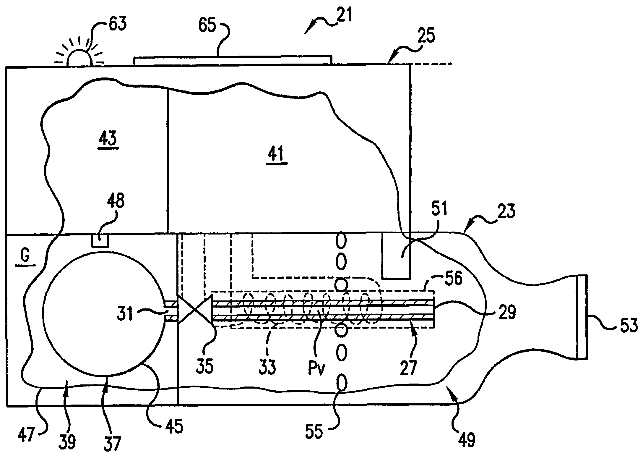
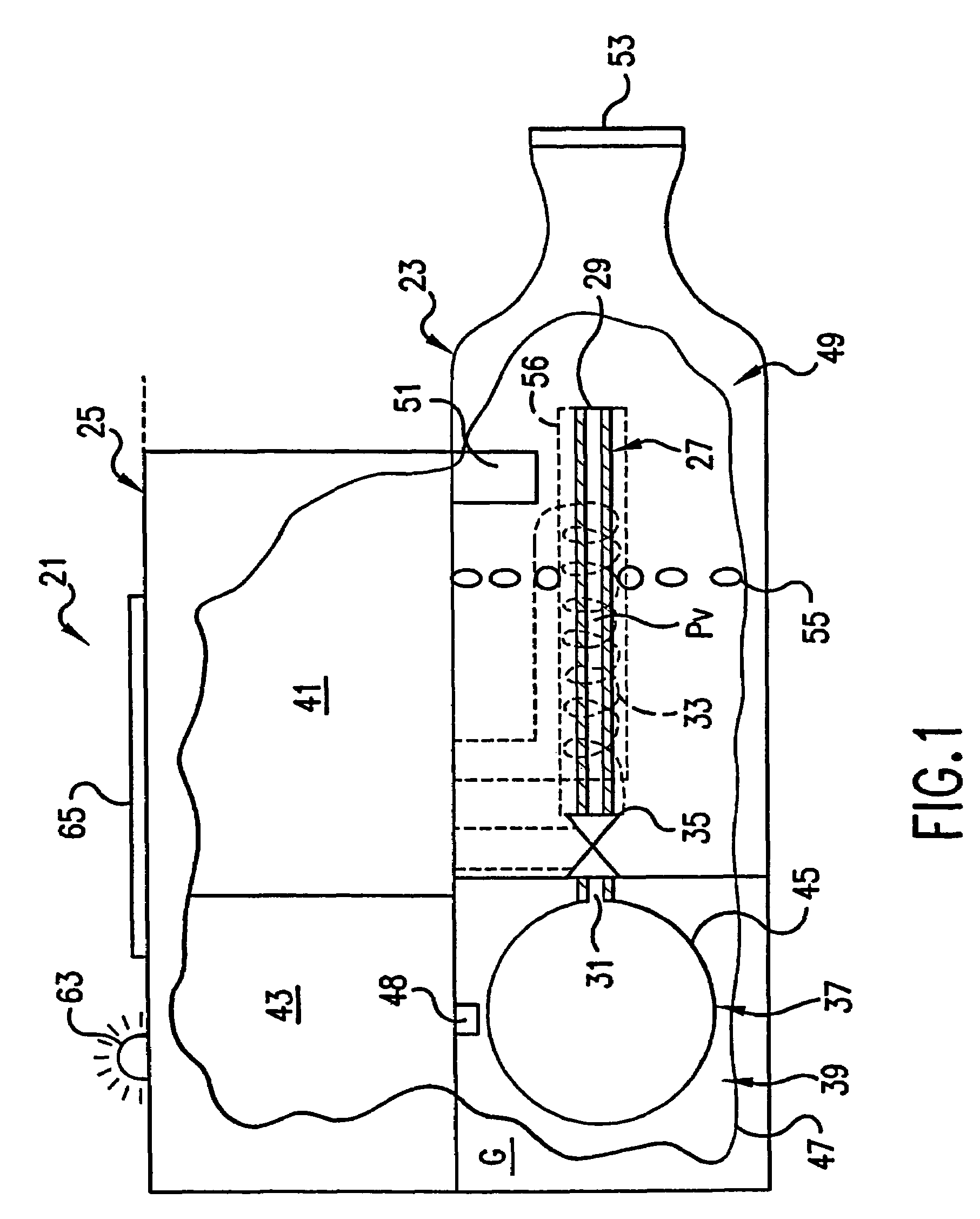
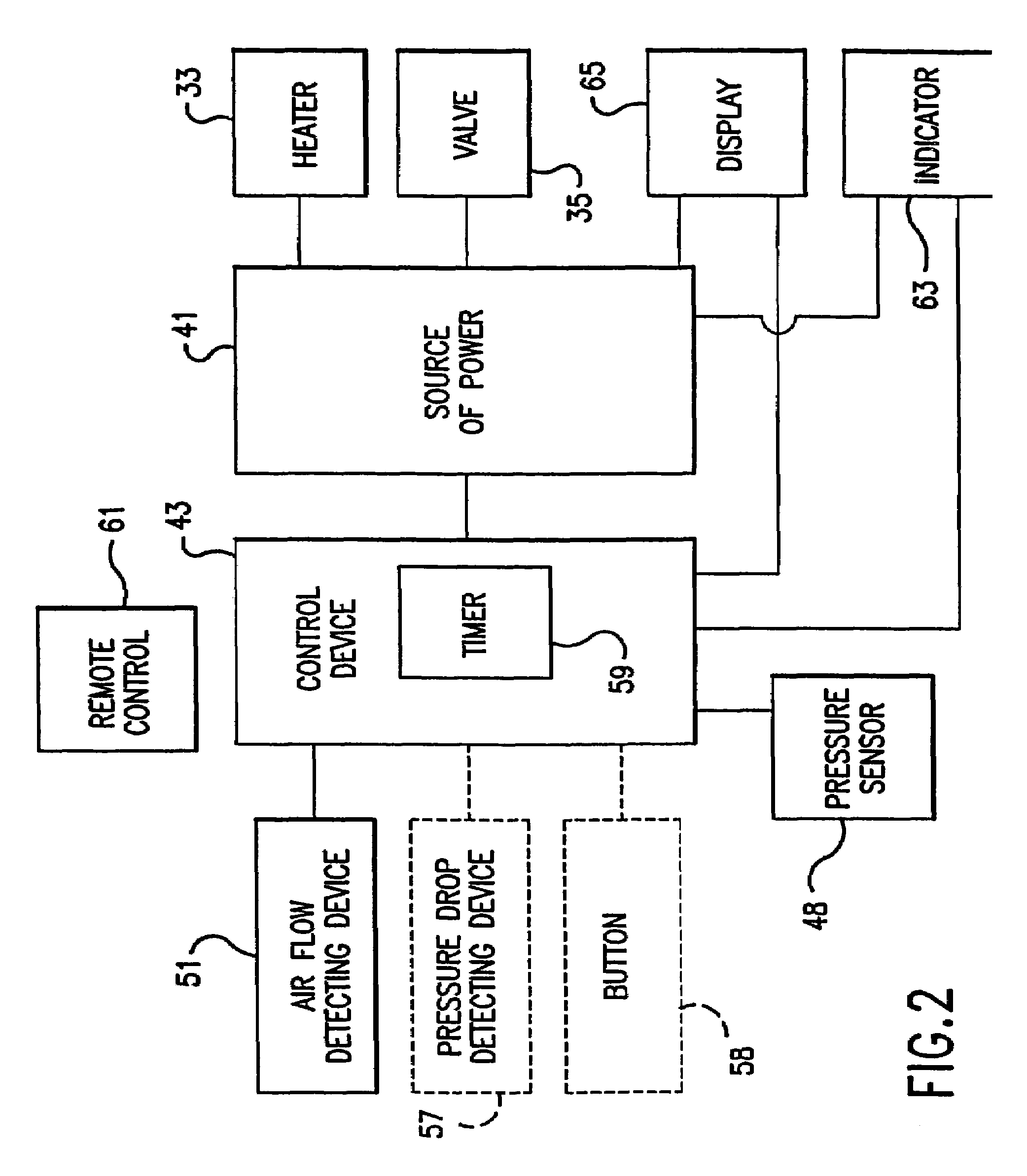
[0032]An aerosol generator 21 according to the present invention is shown in FIG. 1. The principles of operation of the aerosol generator 21 and, where applicable, materials used in the aerosol generator are preferably similar to the principles of operation and materials used in the aerosol generator disclosed in U.S. Pat. No. 5,743,251, which is hereby incorporated by reference in its entirety.

[0033]A preferred application for the aerosol generator 21 is as an inhaler device, such as an inhaler for medicaments, such as asthma medication and pain killers or any other therapeutic agents for treatment of a bodily condition. The aerosol generator 21 preferably includes a first component 23, which preferably includes, for example, the material to be turned into an aerosol and which is preferably disposable after one or a predetermined plurality of uses, removably attached to a second component 25, which preferably includes, for example, power source and logic circuitry structures and wh...


PUM


Abstract

An aerosol generator includes a flow passage having an inlet and an outlet, a heater arranged relative to the flow passage for heating the flow passage, a source of material to be volatilized in communication with the inlet of the flow passage, a valve to open and close communication between the source of material and the inlet of the flow passage, and a pressurization arrangement for causing material in the source of material to be introduced into the flow passage when the valve is in an open position. The aerosol generator further includes a source of power for operating the heater and the valve, and a control device for controlling supply of power from the source of power to the heater and the valve. A metering device in an inhaler includes a pressurized source of medicated fluid and a metering chamber configured to deliver a predetermined volume of fluid to a heated flow passage in the inhaler. The metering chamber can be part of a rotary valve having a bore and a displacement member moveable within the bore from a first position where the fluid is loaded into the bore to a second position where the predetermined volume is ejected out of the bore. Another metering chamber has an elastic portion of a delivery passage in fluid communication with the pressurized source of liquid and the elastic portion of the delivery passage is deformed to eject the predetermined volume.

Description

[0001]This application is a continuation of application Ser. No. 10 / 247,776, filed on Sep. 20, 2002 ABN, which is a continuation of application Ser. No. 0 / 479,597, filed on Jan. 7, 2000 now U.S. Pat. No. 6,516,796, which is a continuation of PCT / US99 / 24080, filed Oct. 14, 1999, which is a continuation of application Ser. No. 09 / 172,023, filed Oct. 14, 1998 now U.S. Pat. No. 6,234,167.BACKGROUND AND SUMMARY OF THE INVENTION[0002]The present invention relates generally to aerosol generators and, more particularly, to aerosol generators able to generate aerosols without compressed gas propellants and methods of making and using such aerosol generators. The present invention also relates generally to metering valves in inhalers and, more particularly, to metering valves which deliver a predetermined volume in inhalers including aerosol generators able to generate aerosols without compressed gas propellants.[0003]Aerosols are useful in a wide variety of applications. For example, it is o...

Claims


Application Information

Patent Timeline
IPC IPC(8): A61M11/00A61M15/00A61M16/00F16K11/00A24F40/10A24F40/30A24F40/48A24F40/485A24F40/50A24F40/60A24F40/65A24F40/70A61M11/04A61M13/00B67D7/02
CPCA61M15/0065A61M15/0003A61M15/008A61M2016/0039A61M2205/10A61M2205/3561A61M2205/3653A61M2205/50A61M2205/52A61M2205/8225A61M11/007A61M11/042A61M15/0066A61M15/0083A24F40/10A24F40/50A24F40/48A24F40/30A24F40/70A24F40/65A24F40/60A24F40/485A61M15/0001A61M11/041A61M39/22A61M2205/33A61M2205/8206
Inventor COX, KENNETH A.BEANE, TIMOTHY PAULSWEENEY, WILLIAM R.NICHOLS, WALTER A.SPRINKEL, JR., F. MURPHY
Owner PHILIP MORRIS USA INC
Learn More