Apparatus for applying a coating to a roof or other substrate

a technology for roofs and substrates, applied in the direction of coatings, liquid spraying apparatus, movable spraying apparatus, etc., can solve the problems of difficult to maintain uniform film thickness, prior art devices suffer from numerous drawbacks, and spraying devices having arced rails are prone to overspray and/or flared out materials at the end of spray path, etc., to achieve efficient, economic and reproducible

Active Publication Date: 2006-10-10
DAVIDSON JAMES W
View PDF15 Cites 15 Cited by
  • Summary
  • Abstract
  • Description
  • Claims
  • Application Information

AI Technical Summary

Benefits of technology

[0011]The spray assembly includes a drive motor which is operable at various speeds controllable by an operator. The drive motor operates an endless drive mechanism which controls movement of a carriage adapted to accommodate a spray gun or other sprayhead operatively connected thereto. The carriage rides in a track formed by at least one rail. The carriage is operatively connected to the drive mechanism by a drive rod which provides for a substantially seamless change of direction of the carriage and allows for precise application of coating.
[0012]In one embodiment, the endless drive mechanism comprises a continuous chain or belt which travels around spaced axles, preferably having sprockets when a chain is utilized. Connected to one segment of the chain is a block and a rod rotatably connected to the rod. The rod is operatively and rotatably connected to the rear of the carriage for driving the same. In one preferred embodiment, an offset rod having offset ends is utilized to provide rapid change of direction of the carriage. The drive mechanism is preferably located in a housing to protect the moving parts. In a preferred embodiment, the carriage is operatively connected to the outside front of the housing and is moved in a substantially horizontal direction. In one embodiment, the carriage comprises slides or wheels which ride or travel in upper and lower rails.
[0014]It is therefore an object of the present invention to provide an apparatus and method capable of applying one or more coatings across a width and length of a substrate in an efficient, economic and reproducible manner.

Problems solved by technology

Although many different types of spray applicators are available, with the known devices it is difficult to maintain uniform film thickness especially when applying a composition which expands or foams during application.
The prior art devices suffer from numerous drawbacks.
Spraying devices having an arced rail often are prone to overspray and / or flared out material at the ends of the spray path.
Accordingly, some prior art devices are not suitable to allow for close proximity spray applications wherein the flare of a coating material would be cast on to an object that is not intended to be covered by the coating.

Method used


Image

  • Apparatus for applying a coating to a roof or other substrate
  • Apparatus for applying a coating to a roof or other substrate
  • Apparatus for applying a coating to a roof or other substrate

Examples


Embodiment Construction

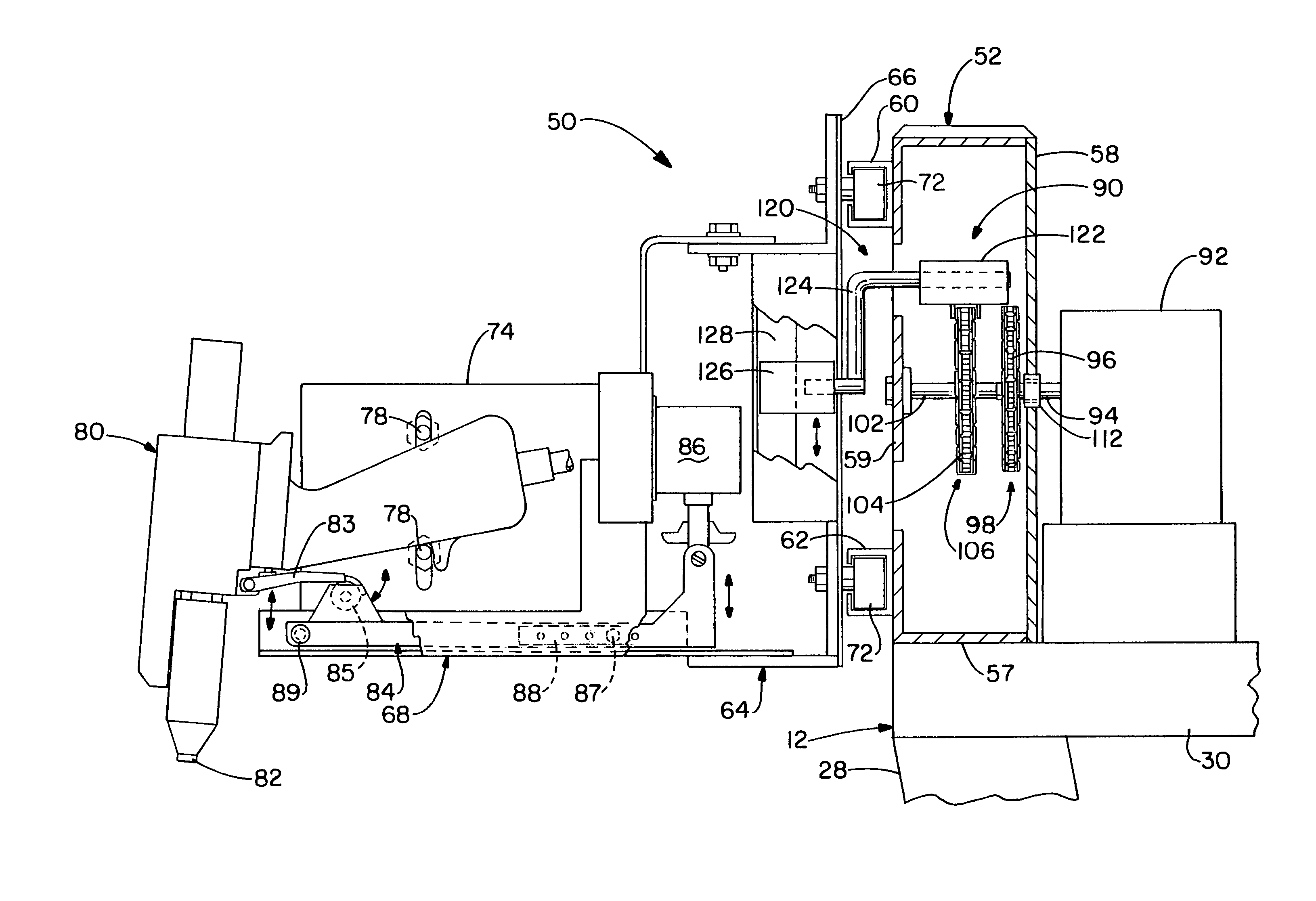
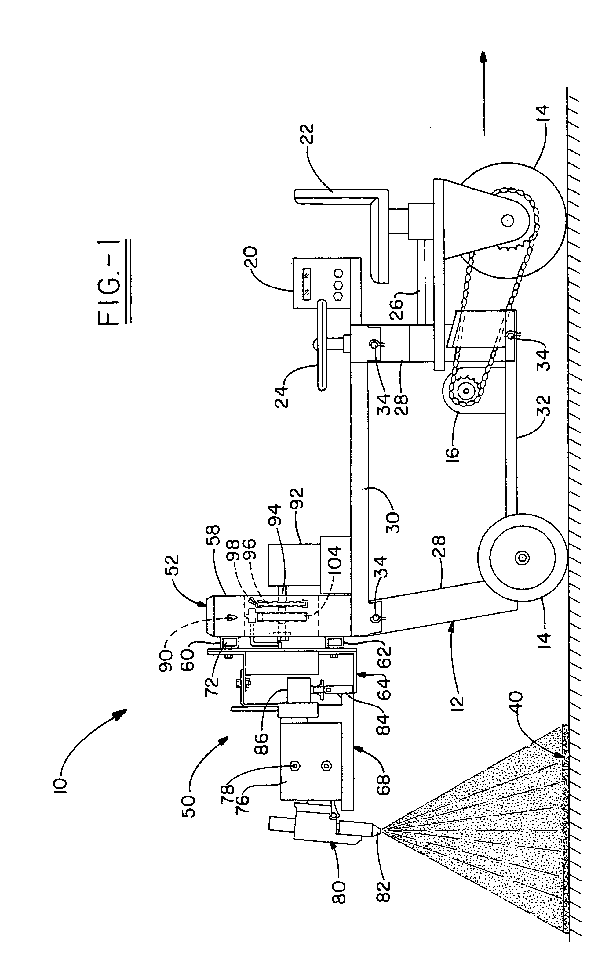
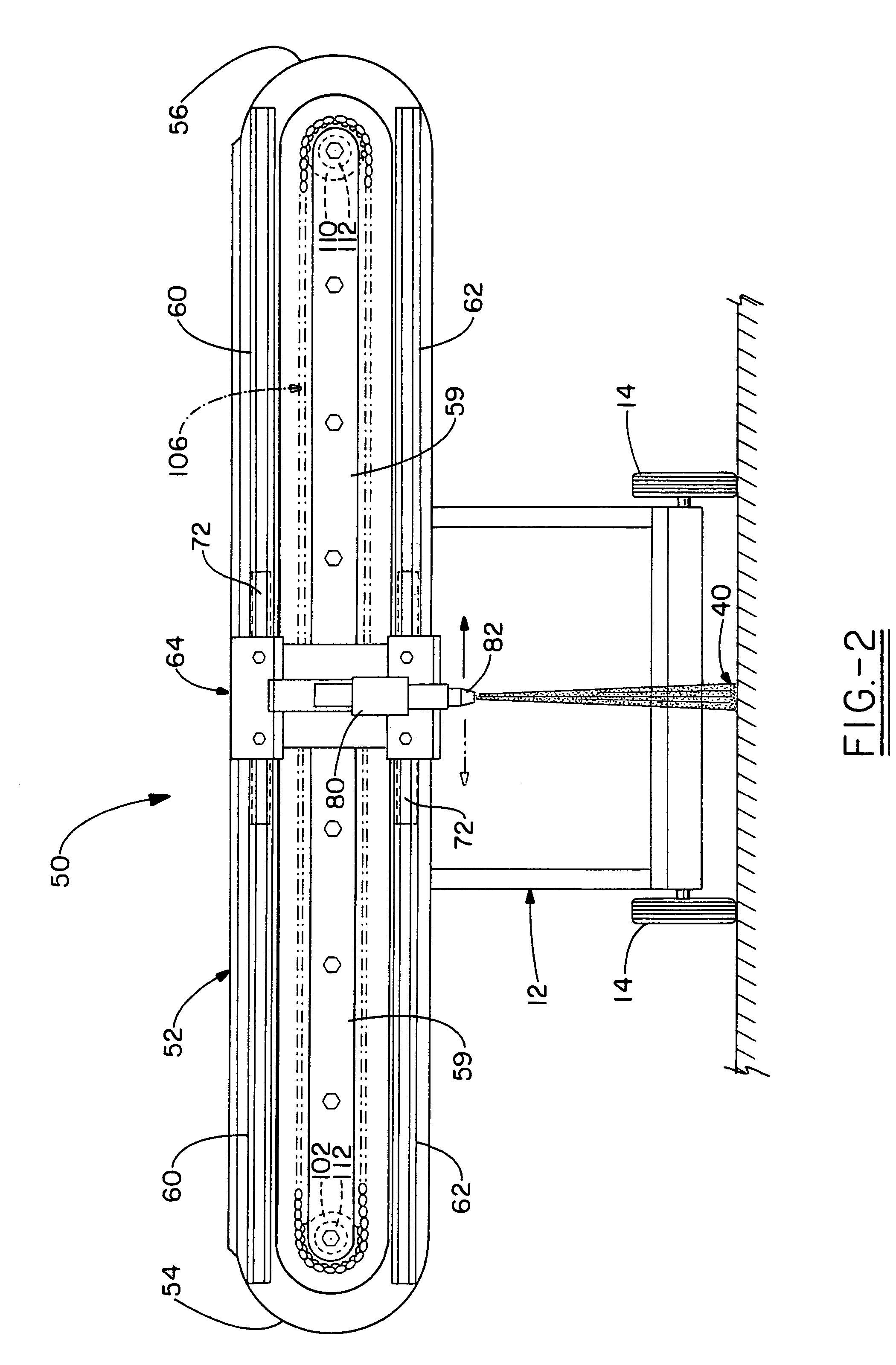
[0023]This description of preferred embodiments is to be read in connection with the accompanying drawings, which are part of the entire written description of this invention. In the description, corresponding reference numbers are used throughout to identify the same or functionally similar elements. Relative terms such as “horizontal,”“vertical,”“up,”“down,”“top” and “bottom” as well as derivatives thereof (e.g., “horizontally,”“downwardly,”“upwardly,” etc.) should be construed to refer to the orientation as then described or as shown in the drawing figure under discussion. These relative terms are for convenience of description and are not intended to require a particular orientation unless specifically stated as such. Terms including “inwardly” versus “outwardly,”“longitudinal” versus “lateral” and the like are to be interpreted relative to one another or relative to an axis of elongation, or an axis or center of rotation, as appropriate. Terms concerning attachments, coupling a...


PUM


Abstract

A device adapted to dispense or spray a coating such as a foam in a predetermined pattern or manner on a substrate, preferably a roof. The spray coating apparatus comprises a spray assembly having a carriage which is operatively mounted on a track that preferably provides a linear travel path. The carriage is controlled by a drive mechanism which causes reciprocating movement of the carriage. A spray gun is mounted on a holder of the carriage and controlled by an actuator and is used to uniformly apply coatings at a predetermined thickness controlled in part by a spray rate on the intended substrate. In one embodiment, the apparatus includes a cart which is either motorized or manual. The apparatus is lightweight and easily disassembled into sections in order to transport the device from a ground surface to a roof.

Description

FIELD OF THE INVENTION[0001]The present invention relates to a device adapted to dispense or spray one or more coatings such as a foam, powder, or liquid in a predetermined pattern or manner on a substrate, preferably a roof. The spraying apparatus comprises a spray assembly having a carriage which is operatively mounted on a track that preferably provides a linear travel path. The carriage is controlled by a drive mechanism which causes reciprocating movement of the carriage with substantially seamless reversal of direction. A spray gun is mounted on a holder of the carriage and controlled by an actuator to uniformly apply coatings at a predetermined thickness controlled in part by a spray rate on the intended substrate. In one embodiment, the apparatus includes a cart which is either motorized or manual in order to apply a coating to a stationary substrate such as a roof, wall, or the like. The apparatus is lightweight and easily disassembled into sections in order to transport th...

Claims


Application Information

Patent Timeline
Patent Type & Authority Patents(United States)
IPC IPC(8): B05B3/12B05B3/18
CPCB05B13/005B05B13/041
Inventor DAVIDSON, JAMES W
Owner DAVIDSON JAMES W
Why Eureka
Try Eureka