Organic el light-emitting element and manufacturing method thereof

a light-emitting element and organic technology, applied in the field of organic light-emitting elements, can solve the problems of difficult production of good quality thin layers, and achieve the effects of low cost, easy manufacturing, and low cos

Active Publication Date: 2020-07-09
SAKAI DISPLAY PROD
View PDF0 Cites 3 Cited by
  • Summary
  • Abstract
  • Description
  • Claims
  • Application Information

AI Technical Summary

Benefits of technology

[0010]According to the first embodiment of the present application, an organic EL light-emitting element is formed with a coated-type organic layer containing an oligomer of an organic material, thereby it is not necessary to subject an insulation bank to a liquid repellent treatment. Thus, a deterioration of the organic layer by fluorine which is contained in a material for a liquid repellent property or introduced in a material by a surface treatment does not occur. Further, since there is no need to form an insulation bank in a reversed tapered shape, manufacturing can be facilitated and an occurrence of a stepwise disconnection of a second electrode can be prevented. A coated-type organic EL light-emitting element is provided in which each pixel of a display apparatus can be constituted by a separate coating of even a very small light-emitting area with a size of, for example, 10 μm square to 50 μm square. Further, according to the second embodiment of the present application, since a coating solution containing an oligomer of an organic material is used and thus a small-sized liquid droplet is ejected and dropped using an ink-jet process, an organic EL light-emitting element in which a coated-type organic layer is formed in a high definition pattern can be provided. Therefore, a precise coating of a small area can be conducted without making a surface of an insulation bank liquid repellent, and a coating solution can be coated uniformly inside an opening. Consequently, a small, high-definition organic EL light-emitting element can be obtained at a low cost and a small, high-definition display apparatus can be manufactured inexpensively.

Problems solved by technology

However, it is difficult to produce a good quality thin layer using a coating process since low molecular weight compounds tend to be easily crystallized.

Method used


Image

  • Organic el light-emitting element and  manufacturing method thereof
  • Organic el light-emitting element and  manufacturing method thereof

Examples


second embodiment

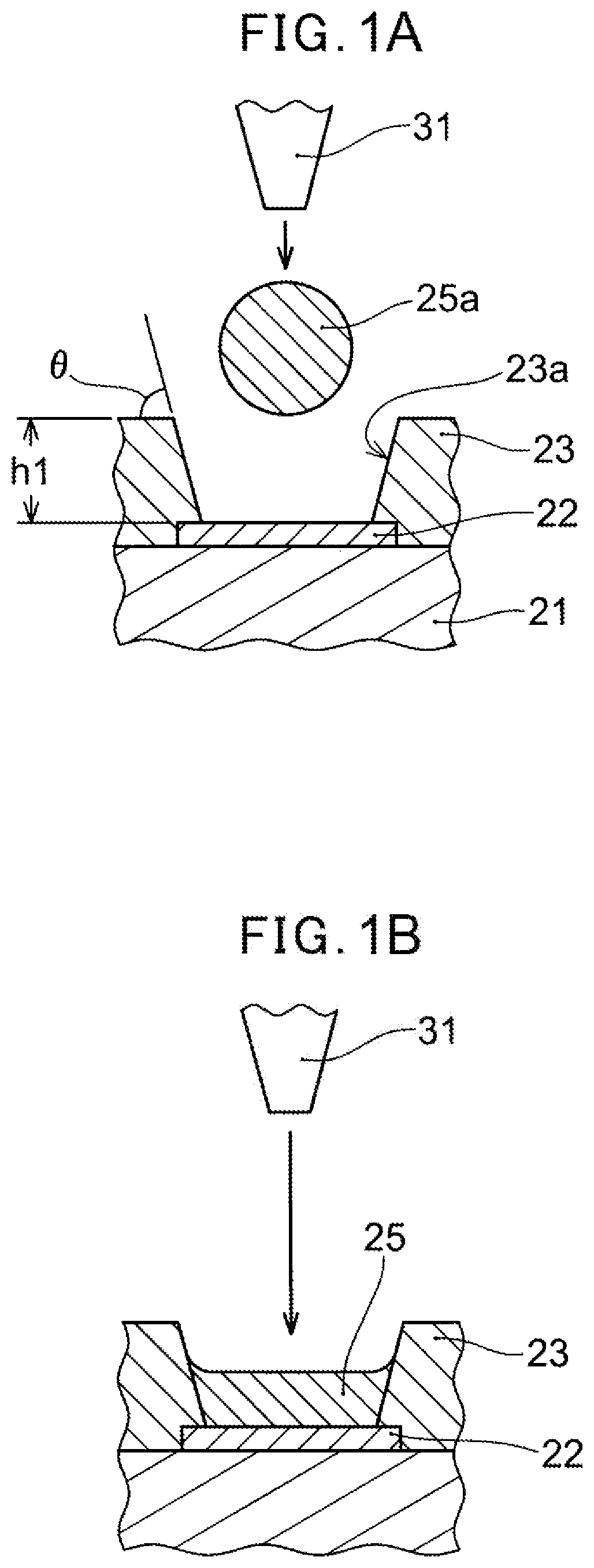
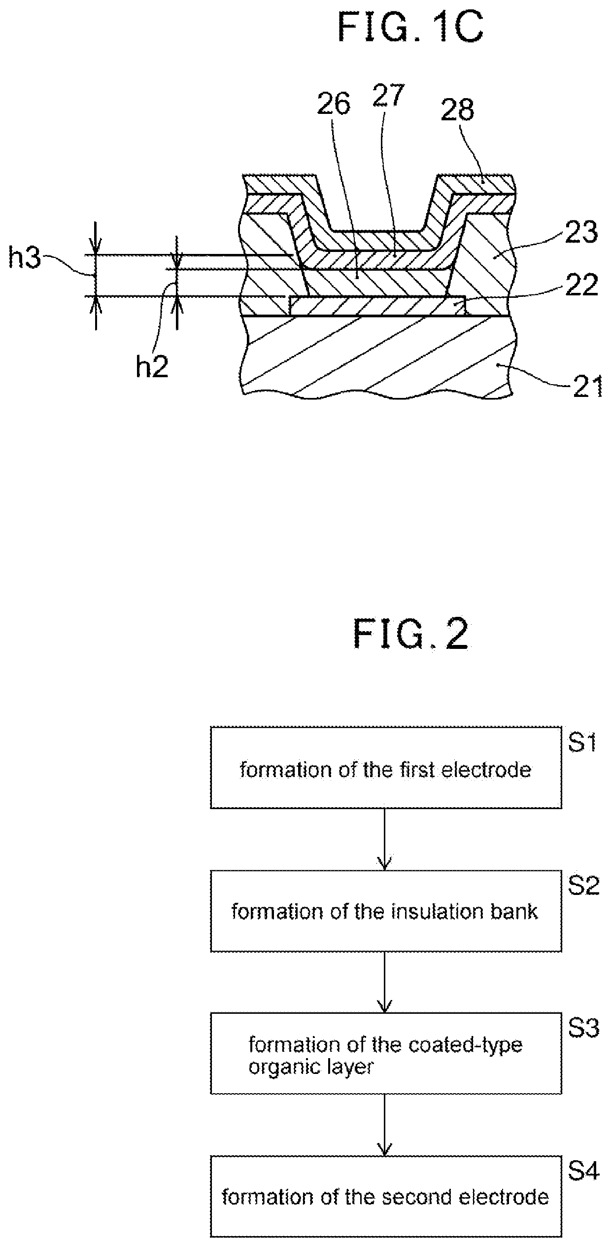
[0051]Referring to a flowchart in FIG. 2, an method of manufacturing an organic EL light-emitting element according to the present application include forming a first electrode 22 on a surface of a substrate 21 (S1), forming an insulation bank 23 to surround at least part of the first electrode 22 (S2), forming a coated-type organic layer 26 on an area of the first electrode 22 surrounded by the insulation bank 23 (S3), and forming a second electrode 27 on the organic layer 26 (S4). To a surface of a sidewall of the opening 23a surrounded by the insulation bank 23 is applied a modifying treatment to increase a hydrophilicity, before forming a coated-type organic layer 26 inside the opening 23a. Further, this organic layer 26 is formed by dropping a droplet of a liquid composition comprising the above described oligomer of an organic material using an ink-jet process. More detailed description will be followed.

[0052]When applying the light-emitting element to an organic EL display ap...

first embodiment

[0061](1) An organic electroluminescent light-emitting element according to the present application includes a substrate, a first electrode provided on a surface of the substrate, an insulation bank formed to surround at least part of the first electrode, an organic layer formed on the first electrode surrounded by the insulation bank, and a second electrode formed on the organic layer, wherein the insulation bank has a forward tapered shape or a sidewall of the insulation bank is formed such as to be substantially perpendicular to the first electrode, and a surface of the insulation bank is formed to have a hydrophilic property, and the organic layer is a coated-type organic layer comprising an oligomer of an organic material.

[0062]According to the organic EL light-emitting element of the exemplary embodiment of the present application, a volume per one drop of a liquid drop of a liquid composition to be ejected form a nozzle of the ink-jet apparatus to form a coated layer can be s...


PUM

PropertyMeasurementUnit
contact angleaaaaaaaaaa
angleaaaaaaaaaa

Abstract

An organic EL light-emitting element is provided in which, by means of an organic material that is oligomeric, an organic layer coated film 25 is formed in a high-definition pixel pattern in the openings 23a of insulation banks 23 that are formed to be hydrophilic; a manufacturing method of said organic EL light-emitting element is also provided. The coated film 25 is formed by dropwise injection of a liquid composition containing an organic material oligomer.

Description

TECHNICAL FIELD[0001]The present disclosure relates to an organic EL light-emitting element (organic electroluminescent light-emitting element) and a method of manufacturing the same.BACKGROUND ART[0002]An organic EL light-emitting element is formed such that a thin layer of organic material containing an organic light-emitting substance is sandwiched between an anode and a cathode. This organic thin layer is formed by a vapor deposition method or a coating method. In a method of manufacturing of a vapor-deposition type organic thin layer, a supporting substrate (a substrate to be vapor-deposited) and a deposition mask are arranged overlapped, an organic material is vapor-deposited in vacuum through an opening of the deposition mask, and a thin layer is formed on the supporting substrate. In general, low molecular weight compounds are used as an organic material for a vapor-deposition type organic material. On the other hand, in a method of manufacturing of a coated-type organic EL ...

Claims


Application Information

Patent Timeline
Patent Type & Authority Applications(United States)
IPC IPC(8): H01L51/00H01L27/32H01L51/50
CPCH01L27/3246H01L51/5012H01L51/0035H01L51/0012H01L51/0005H05B33/10H05B33/12H05B33/22H10K59/122H10K71/135H10K85/111H10K50/11H10K71/191
Inventor KISHIMOTO, KATSUHIKONISHIOKA, YUKIYA
Owner SAKAI DISPLAY PROD
Why Eureka
Try Eureka