

Coating of a glass sleeve
- Summary
- Abstract
- Description
- Claims
- Application Information
AI Technical Summary
Benefits of technology
Problems solved by technology
Method used
Image

Examples
Embodiment Construction
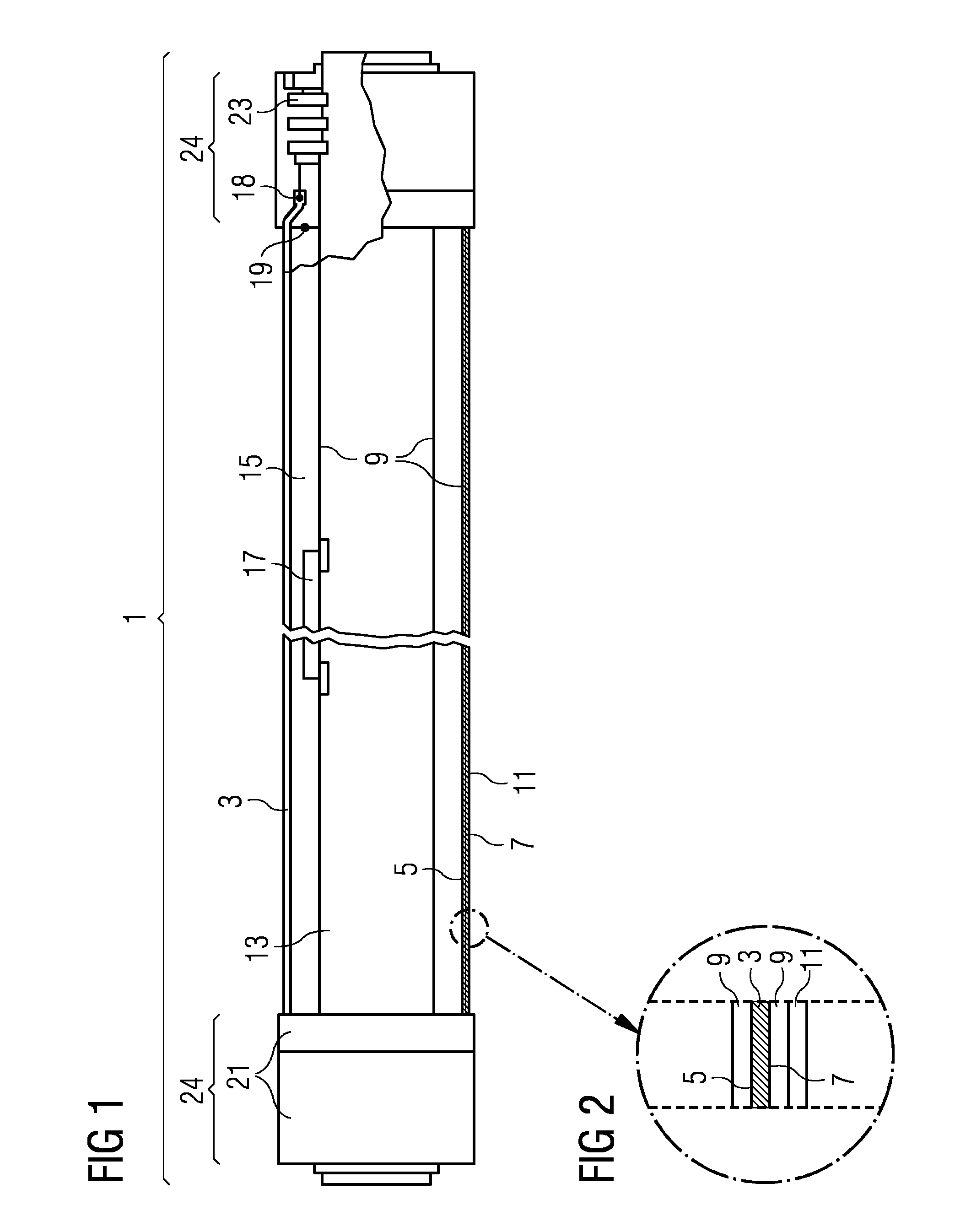
[0058]FIG. 1 shows a cross-sectional view of a solar-receiver tube 1 according to an embodiment of the invention. It comprises a glass sleeve 3 with a diameter 11.5 cm and an absorber tube 13 which has a smaller diameter 7 cm and which extends parallel to the glass sleeve 3. These two tubes are connected to each other by interfaces 24. Those two interfaces 24 are positioned at the end sections of the glass sleeve 3 and of the absorber tube 13 and comprise glass-to-metal seals 18, metal bellows 23, internal shields 19 and external shields 21. Attached to the outer surface of the absorber tube 13 there are getters 17 designed to collect barium and hydrogen particles and thus to maintain a vacuum 15 in the space between the glass sleeve 3 and the absorber tube 13. The solar-receiver tube 1 has a length of 406 cm.
[0059]FIG. 2 shows a cross-sectional view of the wall of the glass sleeve 3 as part of a solar-receiver tube 1, which glass sleeve 3 comprises two types of essentially transluc...
PUM
| Property | Measurement | Unit |
|---|---|---|
| Stress optical coefficient | aaaaa | aaaaa |
| Reflection | aaaaa | aaaaa |
Abstract
Description
Claims
Application Information