Circuit board and method for manufacturing same

Active Publication Date: 2015-07-09
KURARAY CO LTD
View PDF19 Cites 22 Cited by
  • Summary
  • Abstract
  • Description
  • Claims
  • Application Information

AI Technical Summary

Benefits of technology

[0055]According to the present invention, not only by using an adhesive layer comprising a polyphenylene ether-based resin having a low dielectric constant in order to provide adhesion to a liquid crystal polymer film having a low dielectric constant, but also by allowing the adhesive layer to have a specific glass transition temperature, the adhesive layer can provide good adhesion to a circuit layer comprising one or more conductive parts (for example, conductive wiring pattern, in particular conductive wiring pa

Problems solved by technology

The thermoplastic liquid crystal polymer films, however, cannot to be molded by using equipment for multilayer production conventionally used for thermosetting resins because the thermoplastic liquid crystal polymer films require to be heat-treated at a temperature of 250° C. or higher in multilayer lamination process, resulting in requirement for new equipment investment.
However, production of multilayer laminates disclosed in Patent Documents 1 and 2 requires molding at a high temperature as high as around the melting point of the thermoplastic liquid crystal polymer, which is much higher than 200° C. Accordingly, there is a problem that the specific press machine specialized in high temperature application must be used.
As a result, the circuit board may have lowered dimensional stability and poor heat resistance after lamination.
As another problem, the multilayer wiring board cannot be sufficiently resistant to high heat soldering.
However, since the circuit substrate is formed of a thermoplastic resin composition containing a polyphenylene ether-based resin and a thermoplastic resin including a liquid crystal polymer so as to produce a film by melt-kneading the thermoplastic resin composition with an inorganic filler and

Method used


Image

  • Circuit board and method for manufacturing same
  • Circuit board and method for manufacturing same
  • Circuit board and method for manufacturing same

Examples


Example

Application Example 1

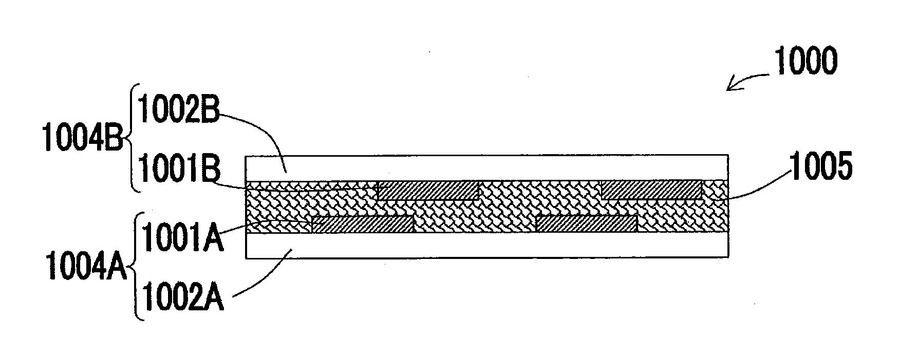
[0209]A rigid-flexible circuit board comprising a flexible part and a rigid part, wherein

[0210]the flexible part comprises a flexible circuit board comprising a film of a thermoplastic liquid crystal polymer capable of forming an optically anisotropic melt phase (hereinafter referred to as a thermoplastic liquid crystal polymer) as an insulating material;

[0211]the rigid part comprises a rigid circuit board comprising:[0212]one or more portions of the flexible circuit board, and[0213]one or more rigid circuit layers disposed to at least on one surface of the flexible circuit board portion(s), the rigid circuit layer(s) each comprising a rigid insulating substrate and one or more conductive parts on at least one surface of the rigid insulating substrate; and

[0214]an adhesive layer comprising a polyphenylene ether-based resin to provide adhesion between the thermoplastic liquid crystal polymer films and between the flexible circuit board portion and the rigid circu...

Example

Application Example 2

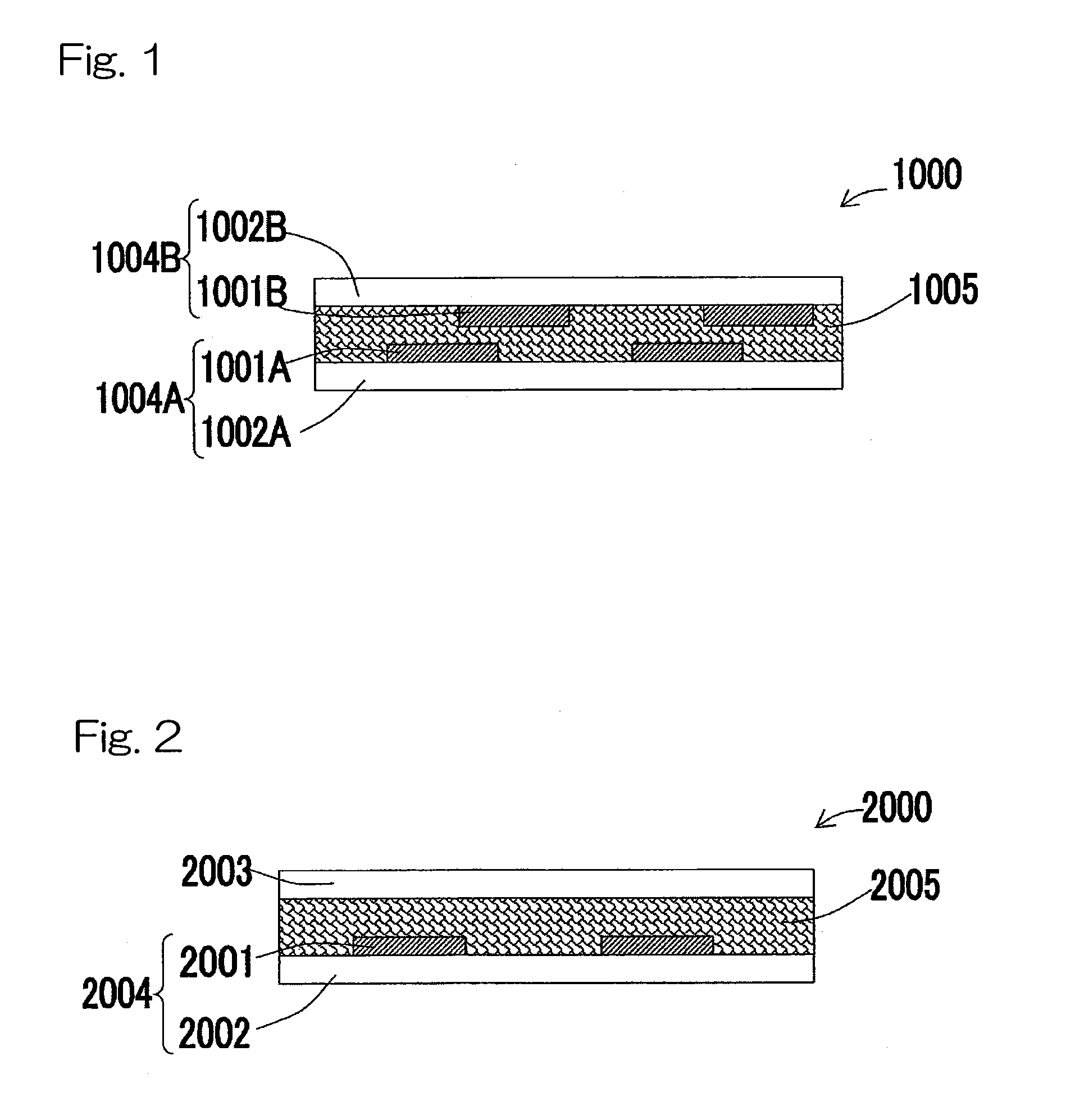
[0215]The rigid-flexible circuit board according to Application Example 1, wherein

[0216]the flexible part is formed of a flexible circuit board comprising:[0217]a flexible insulating substrate formed of a thermoplastic liquid crystal polymer film,[0218]one or more conductive parts disposed on at least one side of the flexible insulating substrate, and[0219]one or more coverlays formed of a thermoplastic liquid crystal polymer film and covering the conductive part(s);

[0220]the rigid part comprises a rigid circuit board comprising:[0221]one or more portions of the flexible circuit board, and[0222]one or more rigid circuit layers disposed to at least on one surface of the flexible circuit board portion(s), the rigid circuit layer(s) each comprising a rigid insulating substrate and one or more conductive part formed on at least one side of the rigid insulating substrate; and

[0223]the adhesive layer comprising a polyphenylene ether-based resin to provide adhesion bet...

Example

[0224]The rigid-flexible circuit board according to Application Example 1 or 2, wherein the thermoplastic liquid crystal polymer has a melting point of 295° C. or higher, and the adhesive layer has a glass transition temperature of 200° C. or higher.


PUM

PropertyMeasurementUnit
Temperatureaaaaaaaaaa

Abstract

Provided is a circuit board being composed of at least a thermoplastic liquid crystal polymer film and an adhesive layer containing a polyphenylene ether-based resin, the circuit board capable of being formed or shaped at a low temperature, and a method of manufacturing the same.
The thermoplastic liquid crystal polymer film constitutes at least one circuit board material selected from the group consisting of an insulating substrate, a circuit layer material and a coverlay. The film is laminated to another circuit board material via the adhesive layer. The glass transition temperature of the adhesive layer is in a range from 200° C. to 300° C.

Description

CROSS REFERENCE TO THE RELATED APPLICATION[0001]This application is a continuation application, under 35 U.S.C. §111(a), of international application No. PCT / JP2013 / 074719, filed Sep. 12, 2013, which claims priority to Japanese Patent Application No. 2012-206412, filed on Sep. 20, 2012, Japanese Patent Application Nos. 2012-230734 and 2012-230735, both filed on Oct. 18, 2012, and Japanese Patent Application No. 2013-002507, filed on Jan. 10, 2013, the entire disclosure of each of which is herein incorporated by reference as a part of this application.FIELD OF THE INVENTION[0002]The present invention relates to a circuit board at least comprising a liquid crystal polymer film comprising a thermoplastic polymer capable of forming an optically anisotropic melt phase (hereinafter sometimes referred to as a thermoplastic liquid crystal polymer film) and an adhesive layer comprising a polyphenylene ether-based resin, the circuit board capable of being formed (molded or laminated) at a low...

Claims


Application Information

Patent Timeline
IPC IPC(8): H05K3/46H05K1/03H05K1/02
CPCH05K3/4602H05K1/0237H05K1/0313H05K3/4611H05K2203/12H05K2201/2063H05K2201/0141H05K2203/06H05K3/4688C09K19/2014C09K19/3087C09K19/322C09K19/3809H05K3/281H05K3/4635H05K3/4691C09K2019/122C09K2219/03
Inventor ONODERA, MINORUMATSUNAGA, SHUJISUNAMOTO, TATSUYASUZUKI, SHIGEAKI
Owner KURARAY CO LTD
Why Eureka
Try Eureka