Power seat sliding device and vehicle seat

Active Publication Date: 2017-09-21
DELTA TOOLING CO LTD
View PDF12 Cites 6 Cited by
  • Summary
  • Abstract
  • Description
  • Claims
  • Application Information

AI Technical Summary

Benefits of technology

[0030]According to the present invention, the driving force transmission mechanism includes the drive unit that consists of a motor for generating a rotation force, as well as the rotating mechanism that is disposed between the drive unit and one of the pair of left and right gear mechanisms so as to be connected to the output shaft of the drive unit and has the function of compensating for the energy loss of the rotation force of the drive unit, and preferably has greater kinetic energy than the rotating parts of the gear mechanisms. This rotating mechanism is able to generate approximately the same level of rotational kinetic energy as that of the drive unit consisting of a motor for generating a rotation force or the second highest level in the driving force transmission mechanism. Thus, the rotation force of the drive unit is supplemented by this rotating mechanism, thereby reducing transmission loss of energy. As a result, a smaller, more lightweight motor can be used as the drive unit.
[0031]The rotating mechanism can be formed using the rotating shaft pivoted between the pair of bearings spaced at a predetermined distance. When the rotational kinetic energy of the drive unit is transmitted to the rotating shaft, the rotating shaft is able to autonomously rotate due to the mass difference between the rotating shaft and the rotating parts (worms) of the gear mechanisms. The rotating shaft is also able to efficiently rotate since it is supported by the bearings. Further, if the auxiliary drive unit consisting of a motor is connected to the rotating shaft, it is possible to store greater kinetic energy than the rotating parts of the gear mechanisms owing to the electric energy of the auxiliary drive unit and thus to further reduce the energy loss of the drive unit. The rotating shaft preferably has a mass that is 1/10 or more of that of the drive unit. If the rotating shaft is connected to the drive unit through the flexible shafts, it serves as a dynamic damper against vibration generated by the drive unit, thereby increasing the vibration absorption function.
[0032]If such a rotating mechanism, in addition to the drive unit, is disposed between the pair of sliders and then the flexible shafts are extended between the respective members, the length of the flexible shafts can be reduced compared to a conventional structure, where one motor alone is disposed between a pair of sliders. Conventional

Problems solved by technology

Thus, gears (worms and worm wheels) forming the gear mechanisms may contact each other and thus make

Method used


Image

  • Power seat sliding device and vehicle seat
  • Power seat sliding device and vehicle seat
  • Power seat sliding device and vehicle seat

Examples


Example

[0091]As with that of the second embodiment, the power seat sliding device of the present embodiment also includes the two rotational force generation mechanisms, the drive unit 220 and auxiliary drive unit 236. Thus, it is possible to reduce the transmission loss of the rotational force using a small, lightweight motor, to suppress vibration, and to reduce unusual sounds caused by vibration or heating attributable to friction, collision, or vibration in the gear mechanisms 210, 210.

Example

[0092]FIGS. 15 to 17 show a fourth embodiment of the present invention. The members having the same functions as the functions of those of the above embodiments are represented by the same reference signs. As described above, bearings 231, 231 are formed of elastic members such as rubber and have, approximately in the center thereof, rotating-shaft penetration holes 231a, 231a in which a rotating shaft 232 is disposed. For this reason, a predetermined region around the rotating-shaft penetration hole 231a supporting a rotating shaft 231 consists of a soft spring region X having a relatively low spring constant. A predetermined region outside that region and around outside penetration holes 231d, 231d having the reinforcing frames 240, 240 inserted therein consists of a hard spring region Y having a relatively high spring constant [see FIG. 17(a)]. The vibration of the rotating shaft 232 can be phase-controlled and damped between these two types of regions. The present embodiment sho...

Example

EXPERIMENTAL EXAMPLE 1

[0097]A vibration sensor was attached to each of a conventional power seat sliding device (Comparative Example 1) and some aspects (Examples 1 to 4) of the power seat sliding device 1 of the present invention, and a vibration level that causes unusual sounds was determined by analyzing the frequency of detection signals of the vibration sensor. The results are shown in FIGS. 18 and 19. FIG. 18 shows the results during a forward movement, and FIG. 19 shows the results during a backward movement.

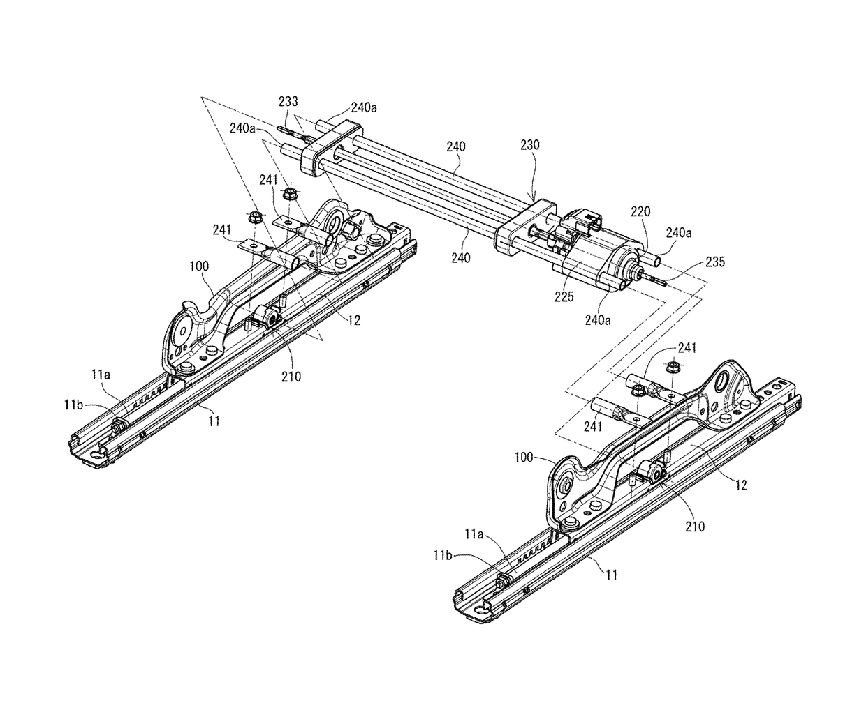
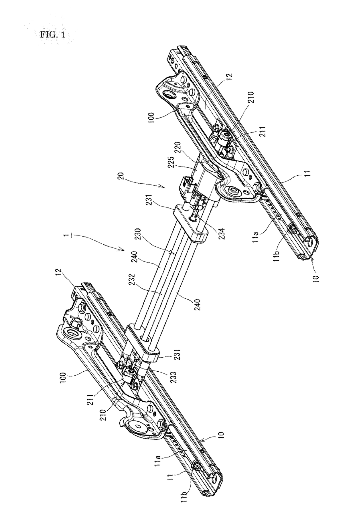
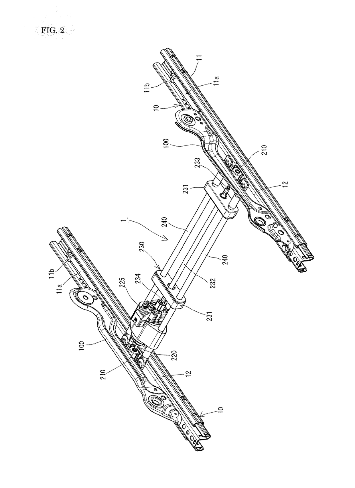
[0098]“Comparative Example” is a conventional power seat sliding device in which a rotating shaft 23 is not used; a supporting steel plate (a center plate) replacing reinforcing frames 240, 240 extends between upper rails 12, 12; and a drive unit 220 and a flexible shaft having a length corresponding to the distance from the drive unit 220 to the other gear mechanism 210 (the right one in FIG. 1) are fixed to and supported by this center plate.


PUM


Abstract

To reduce energy loss to increase power transmission efficiency, as well as to suppress unusual sound resulting from whirling vibration. A driving force transmission mechanism includes a drive unit that generates a rotation force and consists of a motor, as well as an independent rotating mechanism that is disposed between the drive unit and one of a pair of left and right gear mechanisms so as to be connected to the output shaft of the drive unit and has greater kinetic energy than the rotating parts of the gear mechanisms. Flexible shafts that rotate by smaller kinetic energy than any of the kinetic energy of the drive unit, the kinetic energy of the rotating mechanism, and the friction forces and damping forces of the rotating parts of the gear mechanisms connect between the drive unit and rotating mechanism, between the rotating mechanism and one gear mechanism, and between the drive unit and the other gear mechanism.

Description

TECHNICAL FIELD[0001]The present invention relates to a power seat sliding device and a vehicle seat.BACKGROUND ART[0002]As disclosed in Patent Literature 1, there is a power seat sliding device for vehicle seats having the following configuration: slide screws are disposed on, for example, upper rails with brackets therebetween; nut members screwed to the slide screws are disposed on, for example, lower rails; a motor is disposed between left and right sliders; rotation transmission shafts connected to the output shaft of the motor are connected to gear mechanisms disposed on the upper rails; the rotation driving force of the motor rotates the slide screws and changes the positions in which the nut members are screwed to the slide screws; and thus, the upper rails are moved back and forth relative to the lower rails along with the slide screws. Patent Literatures 2 and 3 disclose power seat sliding devices that each use flexible shafts (each consisting of an inner shaft in which st...

Claims


Application Information

Patent Timeline
IPC IPC(8): B60N2/06F16C1/02F16H25/20B60N2/02
CPCB60N2/06B60N2/0232F16H2025/2053F16H25/2021B60N2002/0236F16C1/02F16F15/02F16F15/10F16H25/20B60N2/067B60N2/0705B60N2/0715B60N2/02253B60N2/02258B60N2/02246
Inventor FUJITA, ETSUNORIINOUE, KATSUHIROUMEZAKI, KIYONORI
Owner DELTA TOOLING CO LTD
Why Eureka
Try Eureka