Exhaust gas recirculation device for an internal combustion engine

a technology of exhaust gas recirculation and internal combustion engine, which is applied in the direction of combustion-air/fuel-air treatment, machines/engines, mechanical equipment, etc., can solve the problems of insufficient or defective duct and manifold geometries, inability to meet the requirements of duct and manifold geometry, and the mixing of exhaust gas and air is less effective and uniform, so as to eliminate the shortfall of homogeneity of mixing and reduce the effect of manufacturing and structure simple

Active Publication Date: 2011-02-24
AKWEL SA
View PDF8 Cites 16 Cited by
  • Summary
  • Abstract
  • Description
  • Claims
  • Application Information

AI Technical Summary

Benefits of technology

[0015]The present invention aims to remedy the abovementioned disadvantages, and is configured to eliminate the shortfalls of homogeneity of the mixing between the exhaust gases and the air, particularly in the case of inlet ducts of oblong cross section and of manifolds with flattened inlet and / or flattened plenum, while at the same time retaining the advantages of devices that create swirling vortexes, using a technical solution that is simple in its structure and manufacture and allows all of the kinetic energy of the exhaust gases to be put to good use while at the same time preserving the wall of the inlet duct.

Problems solved by technology

In this context, the problem is that of introducing the exhaust gases into the air inlet duct in such a way that these gases form a uniform mixture with the admitted air before they enter the manifold.
However, it does prove to be defective or insufficient for some duct and manifold geometries, as specified hereinafter.
In such cases, the swirling vortex leaving the tubular mixing nozzle is rapidly destroyed because it is not contained by an external envelope of circular cross section.
The mixing of the exhaust gases with the air is therefore far less effective and less uniform, and the distribution to the engine cylinders, which is performed downstream of this point, may be adversely affected.
An asymmetric phenomenon such as this obviously impairs the distribution of the mixture between the cylinders.
This known embodiment still has disadvantages:By its very principle, it gives rise to a loss in kinetic energy of the recirculated gases at the point where the two swirling vortexes are created, even though these vortexes succeed in retaining a maximum amount of energy to reach the manifold.The two swirling vortexes are not individually confined and guided and simply develop throughout the circular cross section of the inlet duct, coming into direct contact with the wall of the air inlet duct, which thus runs the risk of becoming excessively heated.Following on from the above point, the solution of that document in question is not intended for inlet ducts of oblong or flattened cross section.Finally, the need to have two injection orifices for the recirculated gases, and two separate pipes for carrying these gases as far as the two injection points, makes the structure and manufacture of the device more complicated.

Method used


Image

  • Exhaust gas recirculation device for an internal combustion engine
  • Exhaust gas recirculation device for an internal combustion engine
  • Exhaust gas recirculation device for an internal combustion engine

Examples


Embodiment Construction

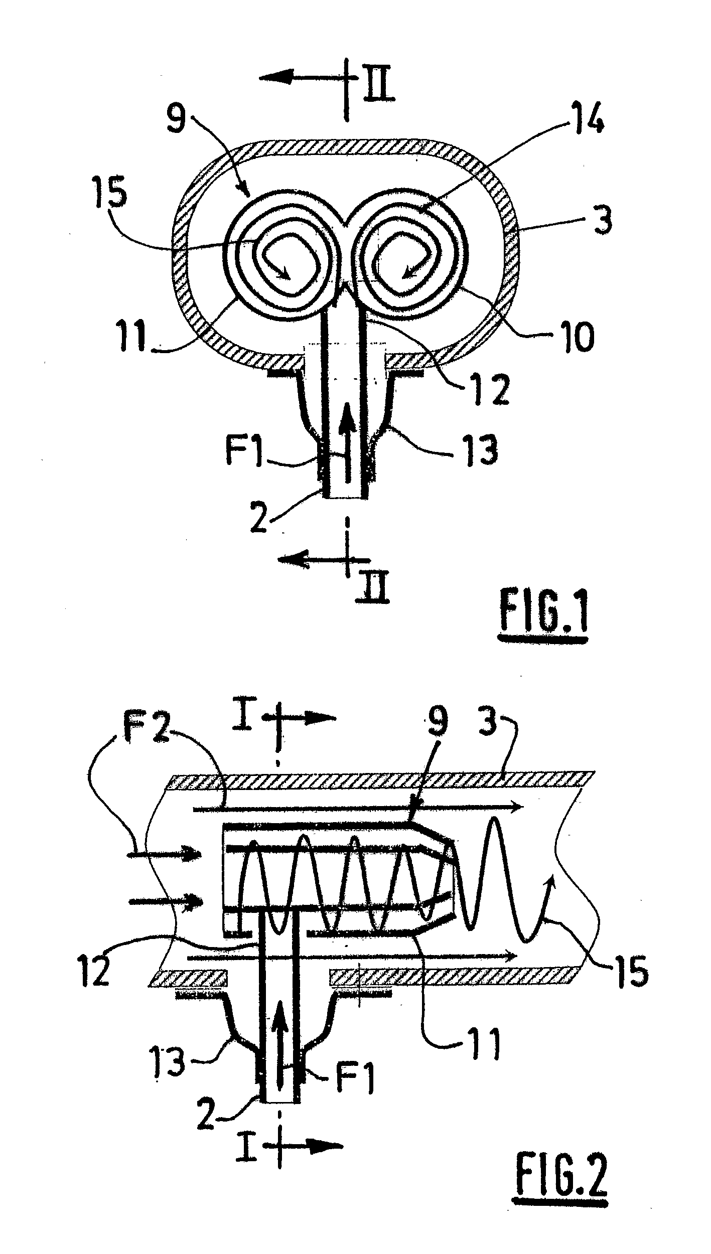
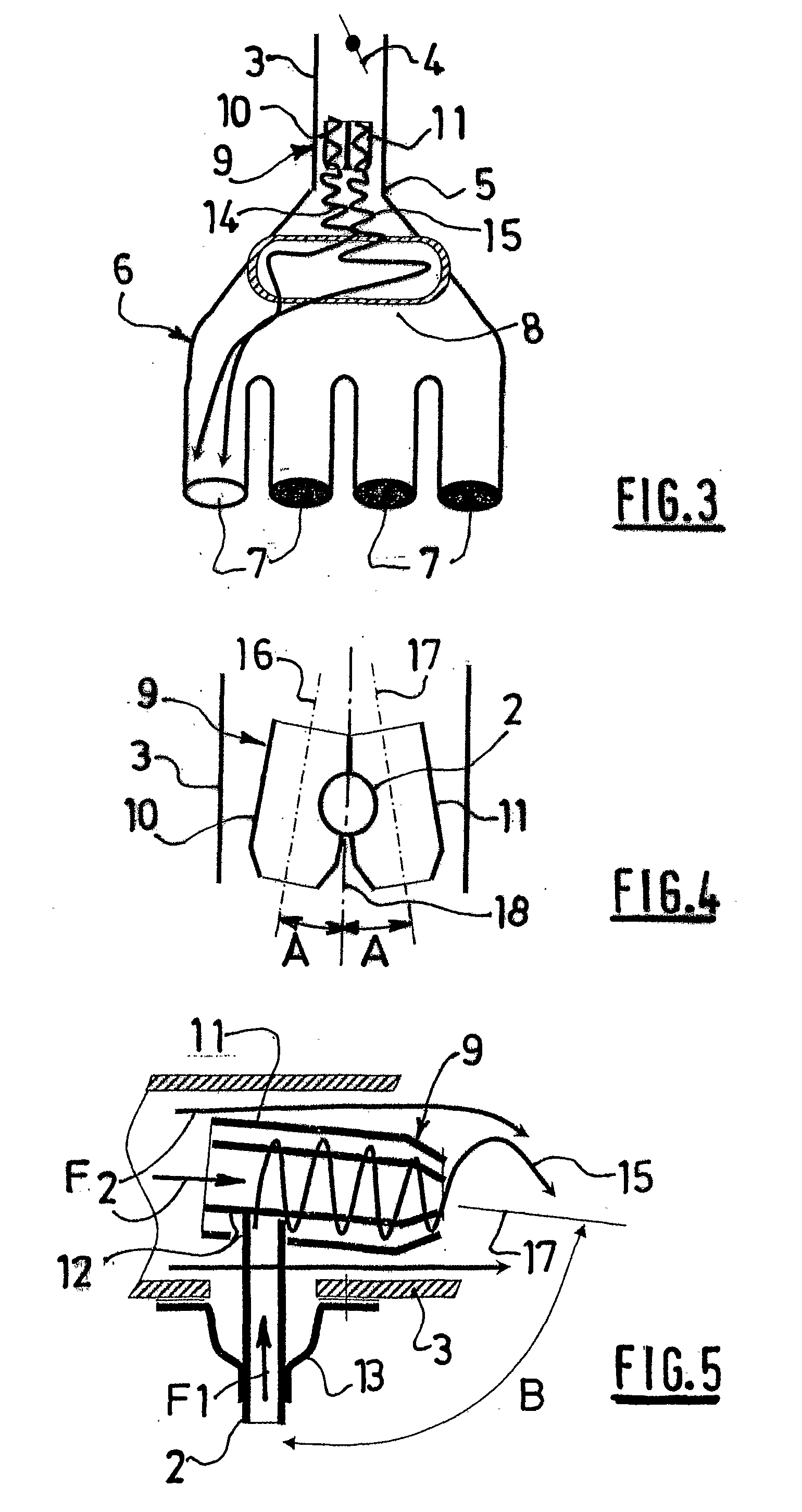
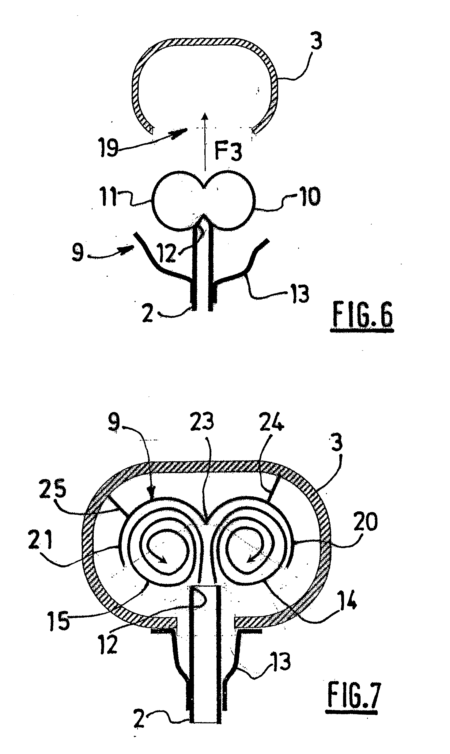
[0040]In the exhaust gas recirculation device depicted schematically in FIGS. 1 to 3, the hot exhaust gases from an internal combustion engine are bled from an exhaust manifold (not depicted) by a pipe 2 which carries them to a fresh air inlet duct 3 of the internal combustion engine, downstream of an air intake flap 4 and upstream of the inlet 5 of a manifold 6 that has numerous outlets 7, for example four outlets, which follows on from the air inlet duct 3. The exhaust gases, arriving in the direction of the arrow F1, are thus mixed with some of the admitted fresh air flow, symbolized by the arrows F2, and the mixture created is directed, by the manifold 6, to the various cylinders of the engine concerned. More particularly, in the exemplary application illustrated here, the air inlet duct 3 has an oblong cross section, as visible in FIG. 1, and accordingly the manifold 6 has an inlet 5 and a plenum 8 both of flattened shape, as symbolized by the cross section indicated as an over...


PUM


Abstract

The recirculation device comprises, inside an air intake duct (3) which is followed by a manifold (6), means for introducing recycled exhaust gases, for mixing same with the fresh air let in. This device is designed to inject the exhaust gases by forming two counter-rotating adjacent vortices (14, 15), owing to a twin tubular mixer nozzle (10, 11) in communication with a common exhaust gas supply duct, positioned tangentially with respect to the two nozzles, placed side by side. The two vortices (14, 15) are self-sustaining to the outlets (7) of the manifold (6). Such a recirculation device is applied, in particular, to an air intake duct (3) of oblong cross section and/or to a manifold (6) with a flattened inlet (5) and/or a flattened plenum (8), in particular for a motor vehicle engine.

Description

TECHNICAL FIELD[0001]The present invention relates to an exhaust gas recirculation device for an internal combustion engine, such as a motor vehicle engine in particular, a device such as this also being known by the abbreviated name of EGR (for exhaust gas recirculation).BACKGROUND[0002]In present-day internal combustion engines it is common-place for hot exhaust gases to be introduced into an air inlet duct at various phases of engine operation according to the speed and load in order to reduce the pollution. The exhaust gases are introduced downstream of the “butterfly” housing in the case of gasoline engines and downstream of the “metering” housing in the case of diesel engines. In all cases, the recirculated gases have to spread uniformly into each cylinder of the engine concerned, because each cylinder has to receive the same amount of external fresh air and of exhaust gas.[0003]Usually, the air inlet system of an internal combustion engine comprises an air inlet duct, of circ...

Claims


Application Information

Patent Timeline
Patent Type & Authority Applications(United States)
IPC IPC(8): F02M25/07
CPCF02M25/0703F02M25/0722F02M29/06Y02T10/146F02M35/10222F02M35/10262Y02T10/121F02M35/10124F02M26/12F02M26/19Y02T10/12F02M35/10
Inventor GUERRY, PASCALMARTINENGO, HERVEDOMINGUEZ, MOISEFERREY, PAUL
Owner AKWEL SA
Why Eureka
Try Eureka