Method for electrostatically separating particles, apparatus for electrostatically separating particles, and processing system

Inactive Publication Date: 2006-10-10
KAWASAKI HEAVY IND LTD
View PDF26 Cites 18 Cited by
  • Summary
  • Abstract
  • Description
  • Claims
  • Application Information

AI Technical Summary

Benefits of technology

[0032]Preferably, the apparatus of the present invention comprises at least one of a meter (load cell or the like) for continuously metering a recovery rate of the insulating particles and a meter (laser beam transmittance meter, contact dust monitor, or the like) for metering amount of the conductive particles that pass through the mesh electrode. This is because, according to the recovery rate or variation in the amount of the conductive particles, which is metered by the meter, the amount of the suctioned gas for recovering the conductive particles,

Problems solved by technology

This inevitably results in wear of the belt and the electrode plates, and these components need to be replaced.
Therefore, a long-time operation is impossible without maintenance.
In the prior art disclosed in Japanese Laid-Open Patent Application Publication No. Hei. 7-75687, there is no function to disperse powdered material adhering to the rotating drum, which would lead to reduced separating capability due to aggregation.
Because of the reduced separating capability, the amount of material to be tr

Method used


Image

  • Method for electrostatically separating particles, apparatus for electrostatically separating particles, and processing system
  • Method for electrostatically separating particles, apparatus for electrostatically separating particles, and processing system
  • Method for electrostatically separating particles, apparatus for electrostatically separating particles, and processing system

Examples


experiment 1

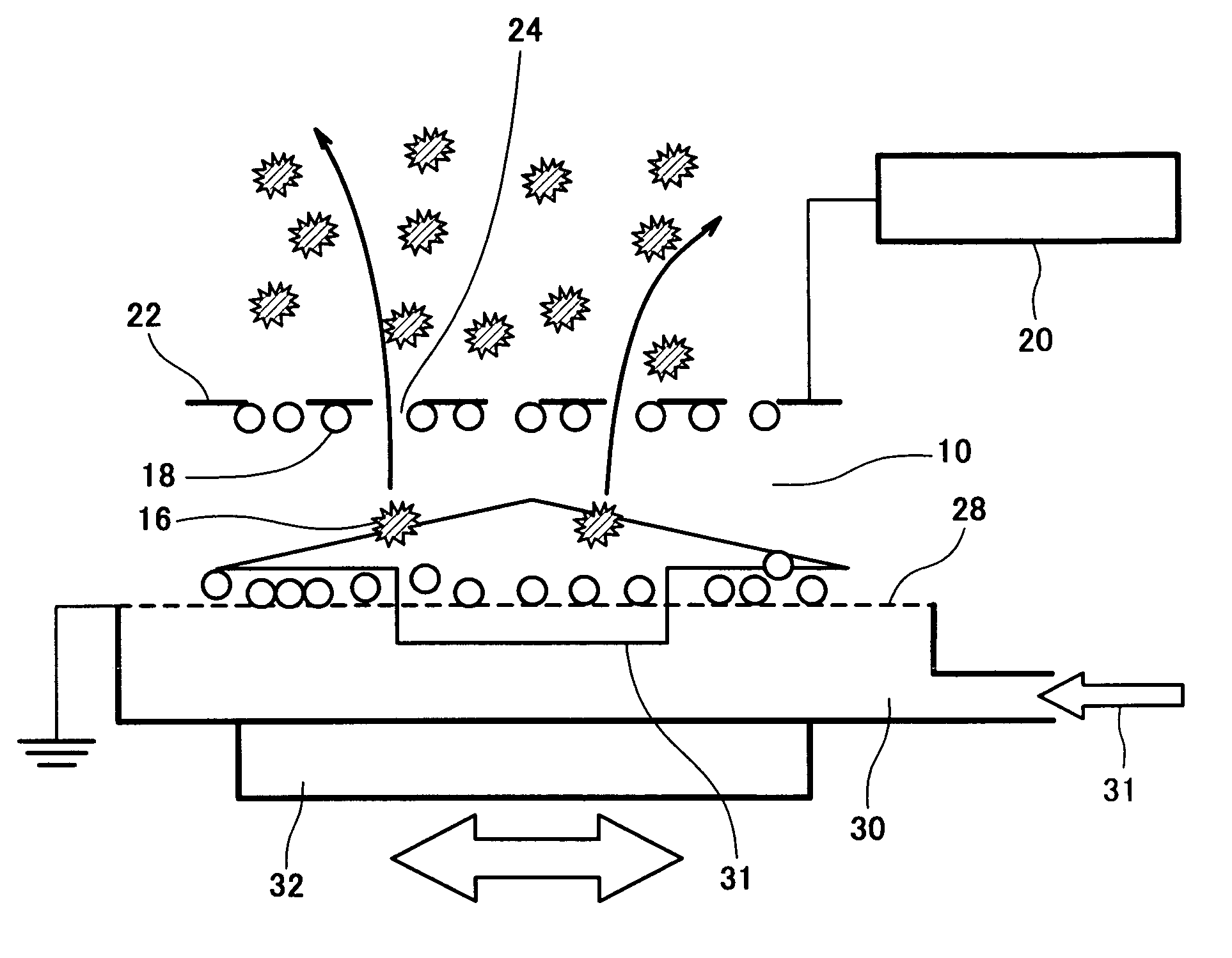
[0077]The electrostatic separation was carried out under the following conditions using the apparatus configured as shown in FIG. 5. The dispersing air was supplied to a dispersing plate (layered sintered porous plate) as positive electrode installed on the bottom at a flow rate of 5 mm / sec, and the entire apparatus was subjected to vibration at an amplitude of 1.5 mm and at a frequency of 25 Hz, a d.c. power supply was connected to the negative electrode provided to be 20 mm distant from the bottom electrode and having meshes of 0.6 mm, a voltage was applied across the electrodes, and under an electric field strength of 0.5 kV / mm, the electrostatic separation was carried out. Under these conditions, using two kinds of coal ash (unburned component=conductive particle weight percentage: 4.2%, 2.3%) as the material, separation of the conductive particles (unburned component) and the insulating particles (ash) was conducted for 10 seconds. The result was that the insulating particles w...

experiment 2

[0078]The electrostatic separation was carried out under the following conditions using the apparatus configured as shown in FIG. 6. Dehumidified dispersing air (dew point:−4° C.) was supplied to a dispersing plate (layered sintered porous plate) as positive electrode installed on the bottom surface at a flow rate of 10 mm / sec, and the entire apparatus was subjected to horizontal vibration in the direction of the insulating particle recovery portion at an amplitude of 1.5 mm and at a frequency of 25 Hz, and four electrodes having meshes of 1 mm and distance of 20 mm between the electrodes were multi-layered above the bottom positive electrode. Among the four electrodes plus the bottom positive electrode, first, third, and fifth electrodes from the bottom were set as positive electrodes (ground potential), minus potential was applied to the second and fourth electrodes, and under the electric field strength between the electrodes set to 0.65 kV / mm, the electrostatic separation was ca...

experiment 3

[0079]The electrostatic separation was carried out under the following conditions using the apparatus configured as shown in FIGS. 7, 8, and 9. Dehumidified dispersing air (dew point:−4° C.) was supplied to the dispersing plate (layered sintered porous plate) as positive electrode installed on the bottom surface at a flow rate of 10 mm / sec, and the entire apparatus was subjected to horizontal vibration in the direction of the insulating particle recovery portion at an amplitude of 1.5 mm and at a frequency of 25 Hz, and four electrodes having meshes of 1 mm and distance of 20 mm between the electrodes were multi-layered above the bottom positive electrode (+). The inclination angle of the electrode was 25°. Among the four electrodes plus the bottom positive electrode, first, third, and fifth electrodes were set as positive electrodes (ground potential), minus potential was applied to the second and fourth electrodes, and under the electric field strength between the electrodes set t...


PUM


Abstract

An electrostatic separation apparatus for conductive particles and insulating particles with reduced separation time and improved separating capability, comprises a substantially flat-plate shaped bottom electrode (26) provided on lower side, a substantially flat-plate shaped mesh electrode (22) provided above the bottom electrode (26) as spaced a predetermined distance apart from the bottom electrode (26) and having a number of openings (24) to allow particles to pass therethrough, a direct current power supply connected to at least one of the mesh electrode (22) and the bottom electrode (24), and a voltage is applied across the bottom electrode (22) and the mesh electrode (24), thereby forming a separation zone (10) between the electrodes.

Description

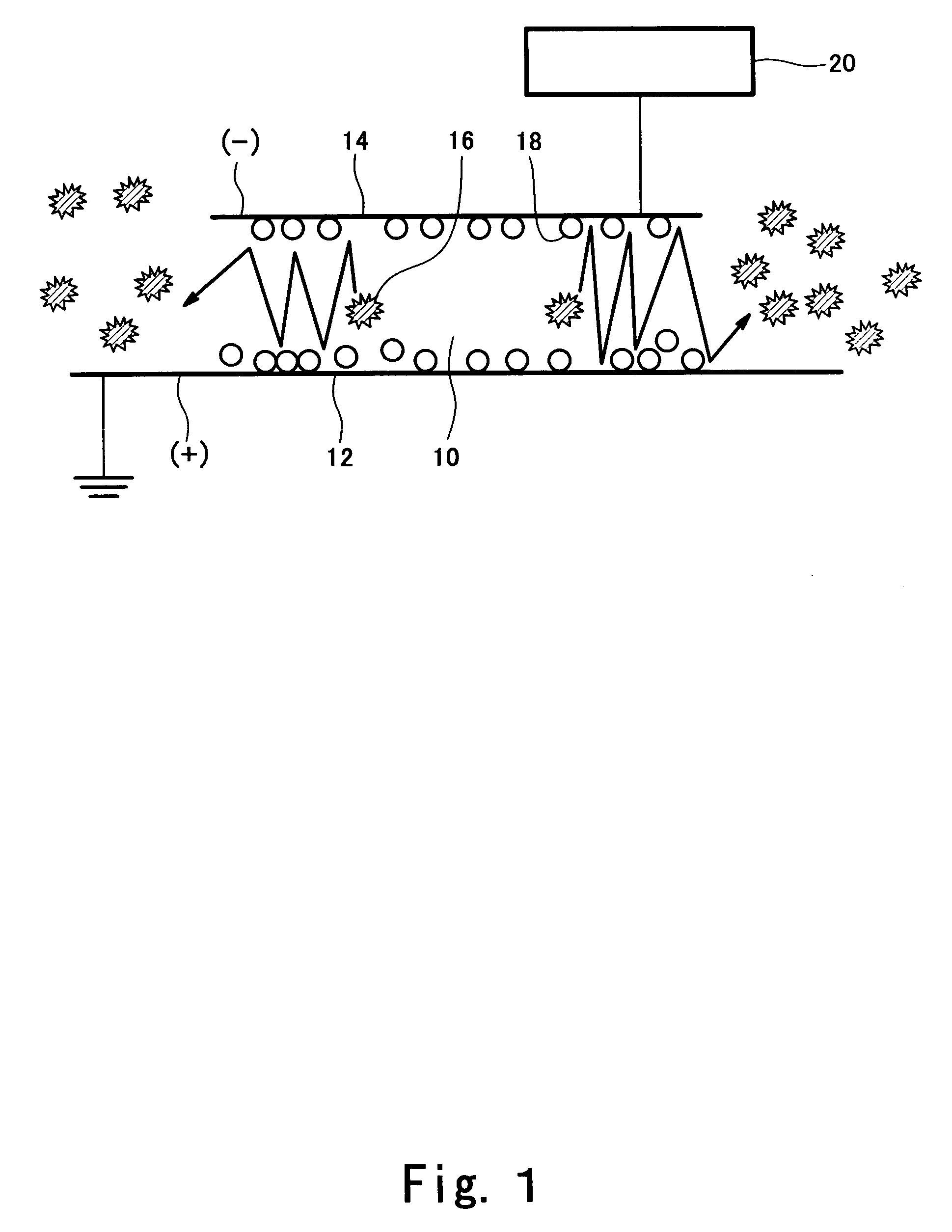
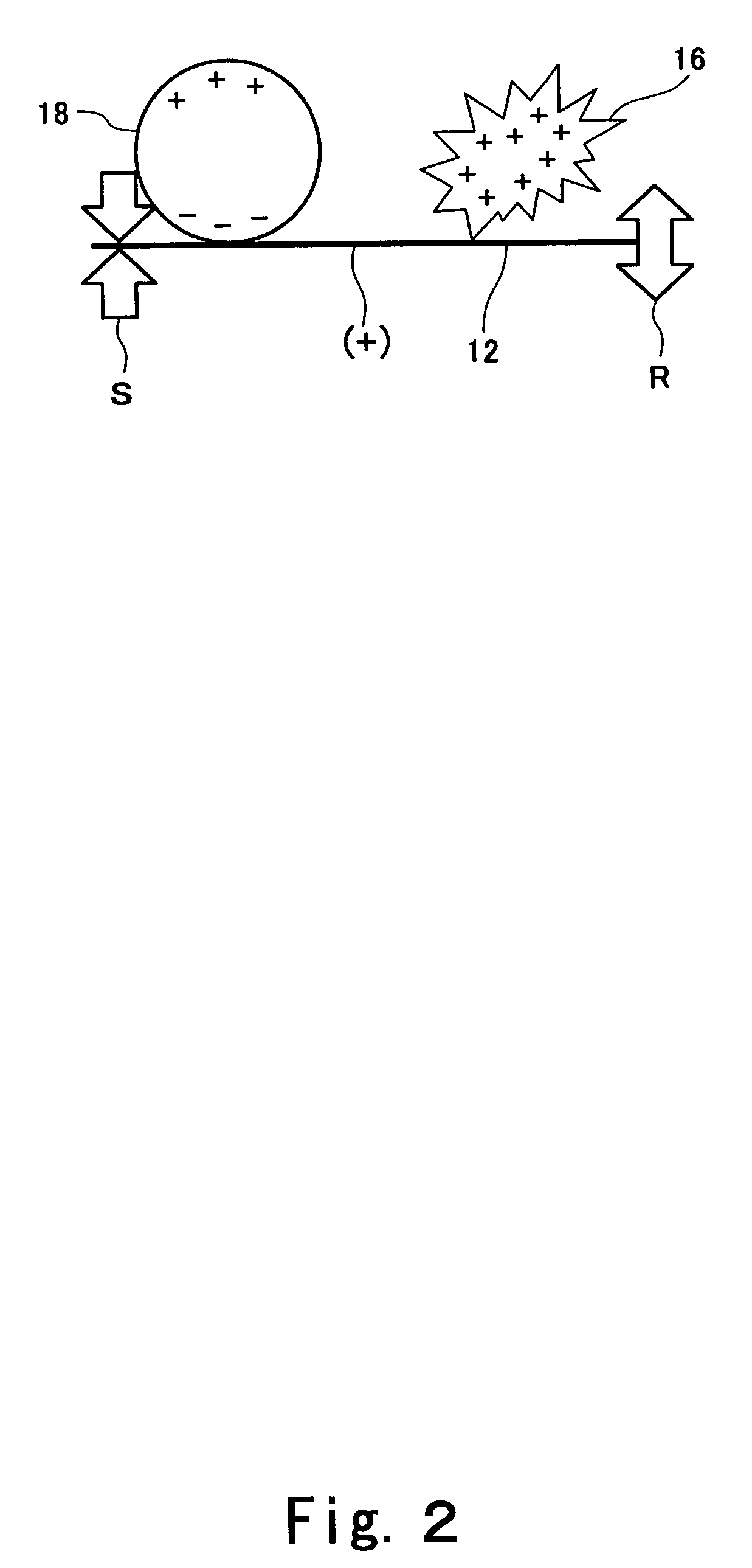
TECHNICAL FIELD[0001]The present invention relates to an electrostatic separation method and an electrostatic separation apparatus used in recycling of wastes such as coal ash derived from a coal-fired boiler, waste plastic, garbage, or burned ash, removal of impurities contained in food, condensing of mineral substances, and the like. More particularly, the present invention relates to a method and apparatus for sufficiently dispersing a material containing electrically-conductive particles and electrically-insulating particles and efficiently separating the electrically-conductive particles from the electrically-insulating particles by an electrostatic force generated by applying a high voltage.BACKGROUND ART[0002]Prior arts described below are known as examples of an apparatus for separating a material containing conductive particles and insulating (non-conductive) particles by an electrostatic force into the conductive particles and the insulating particles.[0003]Published Japan...

Claims


Application Information

Patent Timeline
IPC IPC(8): B03C7/00A23L5/20B03C3/08B03C7/04
CPCB03C3/08B03C7/04
Inventor YOSHIYAMA, EIJISHIBATA, YASUNORIKINOSHITA, TETSUHIRO
Owner KAWASAKI HEAVY IND LTD
Why Eureka
Try Eureka