Controlling a light assembly

a technology for controlling a light assembly and a lamp body, which is applied in the direction of light sources, electrical equipment, instruments, etc., can solve the problems of adversely affecting the mobility of the display device, unfavorable increase in manufacturing costs, etc., and achieve the effect of increasing the load of one lamp

Inactive Publication Date: 2006-10-10
SAMSUNG DISPLAY CO LTD
View PDF16 Cites 33 Cited by
  • Summary
  • Abstract
  • Description
  • Claims
  • Application Information

AI Technical Summary

Benefits of technology

[0012]The invention also includes a method of controlling a light assembly by monitoring a current output from each of a plurality of lamps. Upon detecting a current output exceeding a predetermined magnitude for at least a predetermined time period, a load on one of the lamps is increased. The current output from each of the plurality of lamps is sensed and summed to determine a total current flow through the lamps. Based on the total current flow, current input to the lamps is adjusted.

Problems solved by technology

Accordingly, the artificial light source needs several peripheral devices such as inverters and sensors, which undesirably increase manufacturing cost.
Aside from the associated cost increase, the peripheral devices are undesirable because they increase the volume and the weight of the backlight assembly, adversely affecting the mobility of the display device.

Method used


Image

  • Controlling a light assembly
  • Controlling a light assembly
  • Controlling a light assembly

Examples


Embodiment Construction

)

[0020]Embodiments of the invention are described herein in the context of a LC display device. However, it is to be understood that the embodiments provided herein are just preferred embodiments, and the scope of the invention is not limited to the applications or the embodiments disclosed herein. The present invention will now be described with reference to the accompanying drawings, which portray the preferred embodiments.

[0021]In the drawings, the thickness of layers and regions are exaggerated for clarity. Like numerals refer to like elements throughout. As used herein, a “lamp unit” is a set of one or more lamp subunits and a “current restricting unit” is a set of one or more current restricting subunits.

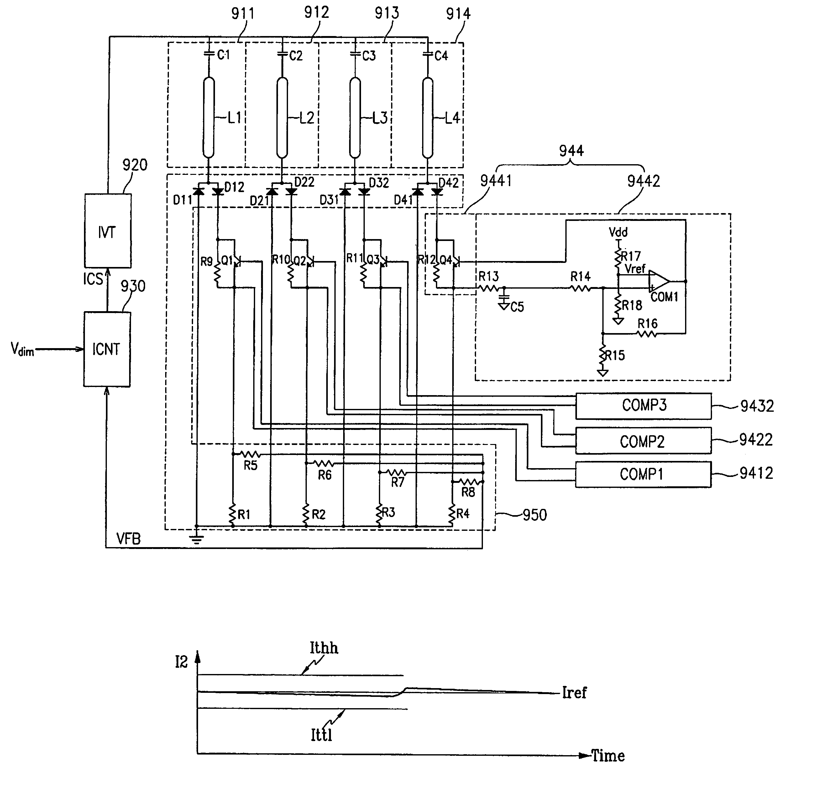
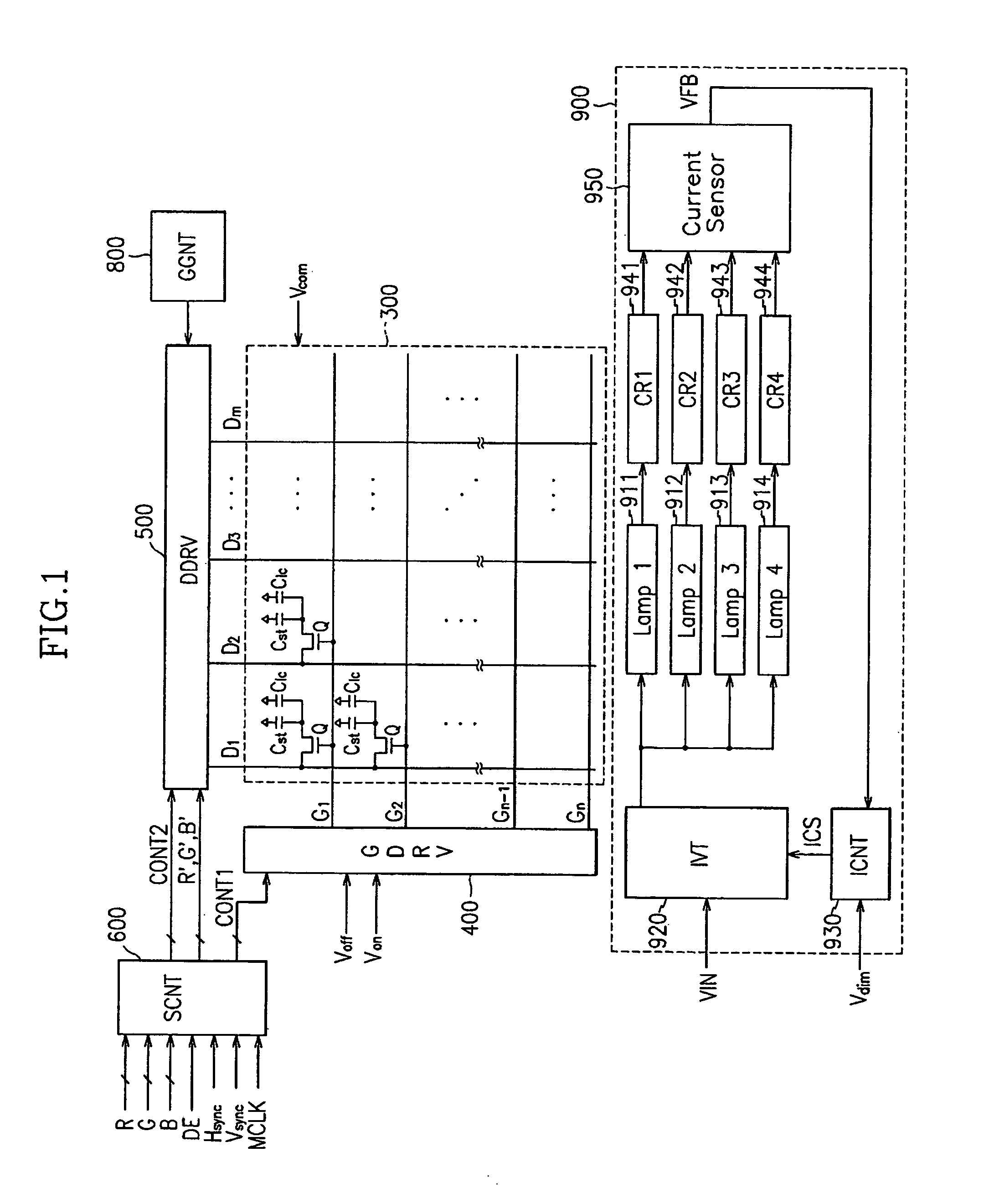
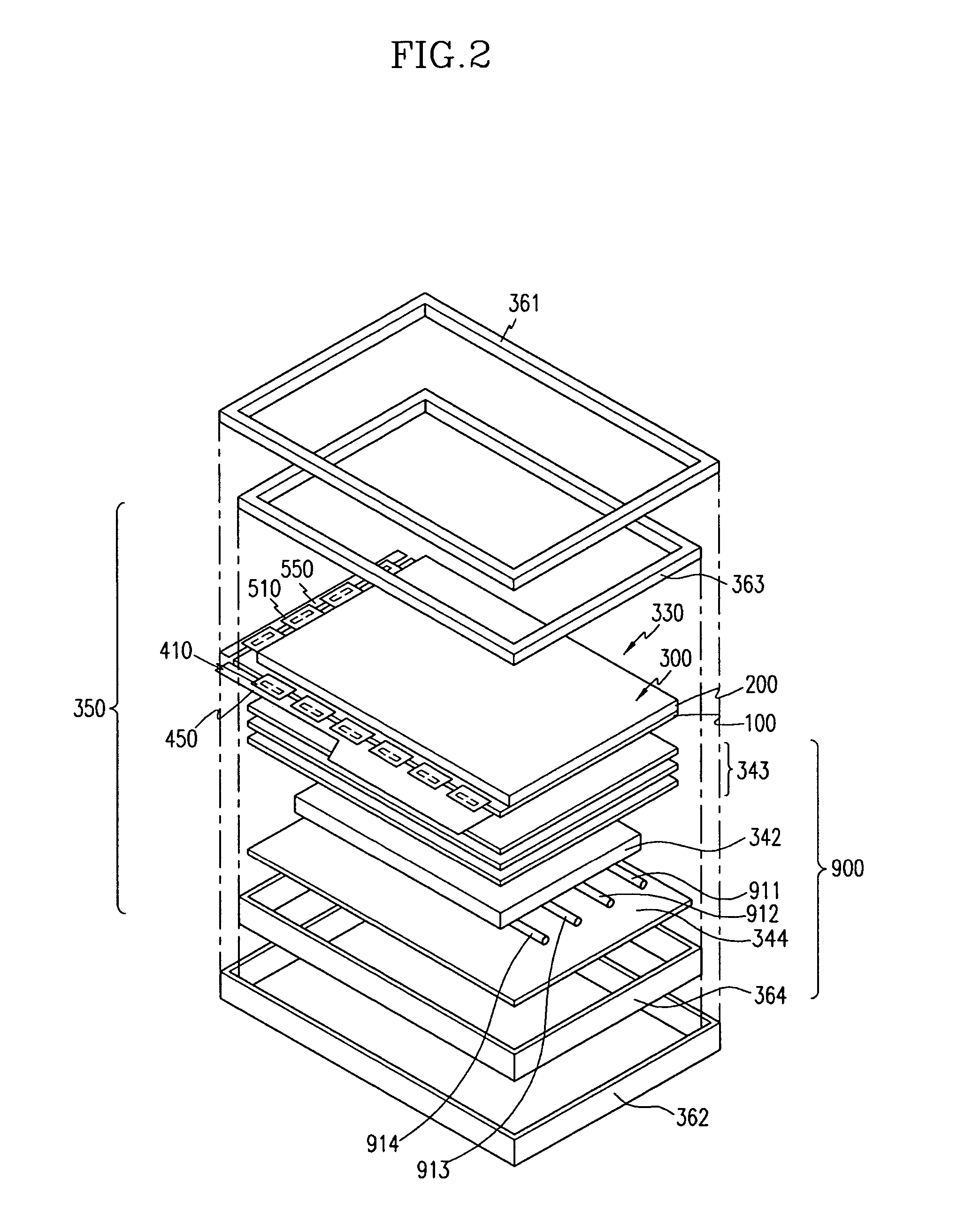
[0022]FIG. 1 is a block diagram of an LCD according to an embodiment of the present invention, FIG. 2 is an exploded perspective view of an LCD according to an embodiment of the present invention, and FIG. 3 is a circuit diagram of a pixel of an LCD according to an embodiment ...


PUM

PropertyMeasurementUnit
currentsaaaaaaaaaa
currentaaaaaaaaaa
currentaaaaaaaaaa

Abstract

A method and apparatus for operating a light assembly with fewer peripheral devices than is currently required is presented. The apparatus of the invention includes a lamp unit, a current restricting unit coupled to the lamp unit, and a current sensing unit that is coupled to the current restricting unit. Upon detecting a current output exceeding a predetermined magnitude for at least a predetermined time period, the current restricting unit increases the load on one of the lamps. The current sensing unit senses the output from each of the lamps as modified by the current restricting unit, and sums the outputs to determine a total current flow through the lamps. A current control unit that is coupled to the current sensing unit uses the total current flow to adjust the current input to the lamps.

Description

RELATED APPLICATION(S)[0001]This application claims priority, under 35 USC § 119, from Korean Patent Application No. 2003-0012678 filed on Feb. 28, 2003, the contents of which are incorporated herein by reference in its entirety.BACKGROUND OF THE INVENTION[0002]1. Field of Invention[0003]The present invention relates to an apparatus for driving a light source for a display device.[0004]2. Description of Related Art[0005]There are various types of display devices that are commonly used for computers and television sets. The types of display devices include self-emitting displays such as light emitting diodes (LEDs), electroluminescence devices (ELs), vacuum fluorescent displays (VFDs), field emission displays (FEDs) and plasma panel displays (PDPs), and non-emitting displays such liquid crystal displays (LCDs). Unlike the self-emitting displays, the non-emitting displays require a light source.[0006]An LCD includes two panels with field-generating electrodes and a liquid crystal (LC)...

Claims


Application Information

Patent Timeline
Patent Type & Authority Patents(United States)
IPC IPC(8): H05B41/36H05B39/04G02F1/13357G02F1/133G09G3/36H05B41/24H05B41/282H05B41/392
CPCH05B41/392H05B41/2822G09G3/36
Inventor JANG, HYEON-YONG
Owner SAMSUNG DISPLAY CO LTD
Why Eureka
Try Eureka