Capacitance difference detecting circuit and MEMS sensor

a detection circuit and capacitance difference technology, applied in the direction of acceleration measurement using interia force, turn-sensitive devices, instruments, etc., can solve the problems of small capacitance change caused by coriolis force, lowered detection sensitivity, failure to detect a small angular speed and acceleration, etc., to achieve the effect of high accuracy and facilitate detection of differen

Active Publication Date: 2006-10-10
MONTEREY RES LLC
View PDF21 Cites 147 Cited by
  • Summary
  • Abstract
  • Description
  • Claims
  • Application Information

AI Technical Summary

Benefits of technology

[0011]According to one of the aspects of the capacitance difference detecting circuit of the present invention, a plurality of oscillators each have a capacitor whose capacitance changes by an external force. Each of the oscillators generates a first oscillating signal according to the capacitance. A detecting unit detects a relative difference between the capacitances of the capacitors as a difference between frequencies of the first oscillating signals. This allows detection of a minute difference in the capacitances with high accuracy.
[0025]According to another aspect of the capacitance difference detecting circuit of the present invention, a pair of oscillators each have a capacitors whose capacitance changes according to an external force and generate a first oscillating signal according to the capacitances. A pair of PLL circuits have voltage controlled oscillators and receive the first oscillating signals from the oscillators to output second oscillating signals from the voltage controlled oscillators respectively. A detecting unit receives input voltages to be inputted to the respective voltage controlled oscillators of the PLL circuits. The input voltages are adjusted in accordance with the frequencies of the first oscillating signals and of the second oscillating signals. The detecting unit detects a difference between the received input voltages as a relative difference between the capacitances. In other words, the detecting unit detects the relative difference between the capacitances of the capacitors as the difference between the input voltages, which allows detection of a minute capacitance difference with high accuracy.

Problems solved by technology

However, the capacitance of a capacitor as a constituent of the MEMS sensor is also small, so that an amount of change in the capacitance caused by the coriolis force is small.
This results in lowered detection sensitivity.
This may cause a failure in detection of a small angular speed and acceleration.
Therefore, it is not possible to form a capacitance difference detecting circuit that detects a difference between capacitances of two capacitors that change by an external force.
Nor is it possible to form a MEMS sensor having two capacitors between a substrate and a mass body to detect an angular speed or acceleration according to capacitances each changing according to the coriolis force.

Method used


Image

  • Capacitance difference detecting circuit and MEMS sensor
  • Capacitance difference detecting circuit and MEMS sensor
  • Capacitance difference detecting circuit and MEMS sensor

Examples


Embodiment Construction

[0041]Hereinafter, embodiments of the present invention will be described, using the drawings. Signals supplied via external terminals are designated by the same reference numerals and symbols as the names of the terminals. Further, signal lines through which signals are transmitted are designated by the same reference numerals and symbols as the names of the signals.

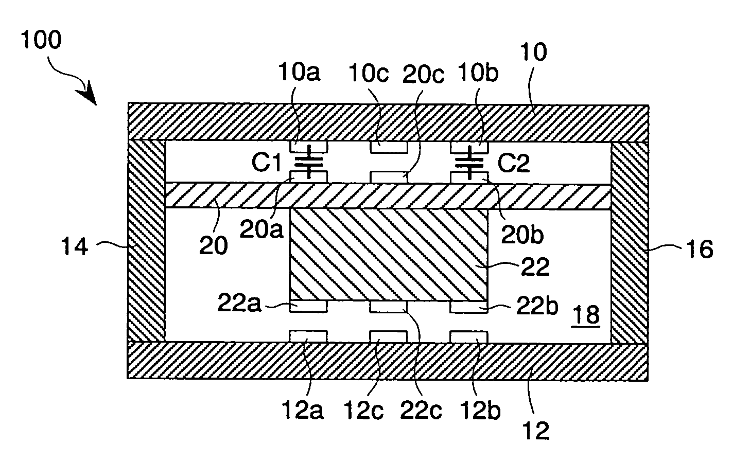
[0042]FIG. 1 shows a MEMS unit 100 that is an essential part of a first embodiment of the capacitance difference detecting circuit and the MEMS sensor of the present invention. The capacitance difference detecting circuit and the MEMS sensor are formed on a semiconductor substrate such as a silicon substrate through the use of semiconductor manufacturing technology (for example a CMOS process). In this embodiment, the MEMS sensor is a so-called uniaxial sensor and it has the MEMS unit 100 and a capacitance difference detecting circuit 200 shown in FIG. 4. The MEMS sensor is applied as, for example, a sensor for actuatin...


PUM


Abstract

Oscillators have capacitors, respectively, whose capacitances change according to an external force and generate first oscillating signals according to the capacitances. Each of the capacitors is disposed, for example, between a substrate and a mass body that is movably disposed to face the substrate and oscillates in a direction perpendicular to the substrate. A detecting unit detects a relative difference between the capacitances of the capacitors as a difference between frequencies of the first oscillating signals. An angular speed or acceleration applied in a horizontal direction of the substrate is calculated according to the frequency change detected by the detecting unit. Therefore, a capacitance difference detecting circuit and a MEMS sensor that detect a minute change in the capacitances of the two capacitors caused by the external force are formed.

Description

CROSS REFERENCE TO RELATED APPLICATION[0001]This application is based upon and claims the benefit of priority from Japanese Patent Application No. 2004-144906, filed on May 14, 2004, the entire contents of which are incorporated herein by reference.BACKGROUND OF THE INVENTION[0002]1. Field of the Invention[0003]The present invention relates to a capacitance difference detecting circuit that detects a change in capacitances of two capacitors and a MEMS sensor that detects an applied angular speed or acceleration according to the change in the capacitances of the two capacitors.[0004]2. Description of the Related Art[0005]In recent years, MEMS sensors (an angular speed sensor and an acceleration sensor) formed by MEMS (Micro Electro Mechanical Systems) are in practical use. The MEMS sensors of this type have a substrate, a mass body disposed displaceably relative to the substrate and oscillating in a vertical direction of the substrate, and two capacitors formed between the substrate ...

Claims


Application Information

Patent Timeline
Patent Type & Authority Patents(United States)
IPC IPC(8): G01R27/26G01P9/04G01C19/56G01D5/24G01D5/241G01P15/125
CPCG01C19/56G01P15/125G01D5/24G01P2015/084G01R27/26
Inventor KITANO, MAYOSUMI, HIDEKIMORIBE, TSUYOSHI
Owner MONTEREY RES LLC
Why Eureka
Try Eureka