Transflective LCD device having dual thickness color filter

Inactive Publication Date: 2006-10-10
LG DISPLAY CO LTD
View PDF8 Cites 3 Cited by
  • Summary
  • Abstract
  • Description
  • Claims
  • Application Information

AI Technical Summary

Benefits of technology

[0023]An object of the present invention is to provide a color filter substrate of a transflective liquid crystal display device to produce uniform color purity and uniform color reproduction.
[0024]Another object of the present invention is to provide a method of fabricating a color filter substrate of a transflective liquid crystal display device to produce uniform color purity and uniform color reproduction.
[0025]Another object of the present invention is to provide a transflective liquid crystal display device having an easily controllable buffer layer pattern in order to control a color filter thickness in a transmissive

Problems solved by technology

In addition, the transmissive-type LCD device requires a relatively high initial brightness, whereby electrical power consumption by the backlight device increases.
Accordingly, a relatively heavy battery, which cannot be used for an extended period of time, is needed to supply sufficient power to the backlight device.
However, the reflective-type LCD device is easily affected by its surroundings.
For example, since ambient light in an office differs largely from that of the outdoors, the reflective-type LCD device can not be used where the ambient light is weak or does not exist.
Since the color filter resin is a viscous material, the thickness of the color filter resin is hard to control and can not be fabricated at less than a specific thickness.
However, if the color filter layers of the reflective and transmissive portions are formed of different materials, the process time and production costs would increase, thereby decreasing yield of the display device.
Although the transmittance for the red colored light is high, the transmittances for the other colors are not negligible such that color pu

Method used


Image

  • Transflective LCD device having dual thickness color filter
  • Transflective LCD device having dual thickness color filter
  • Transflective LCD device having dual thickness color filter

Examples


Example

[0047]Reference will now be made in detail to the preferred embodiments of the present invention, example of which is illustrated in the accompanying drawings.

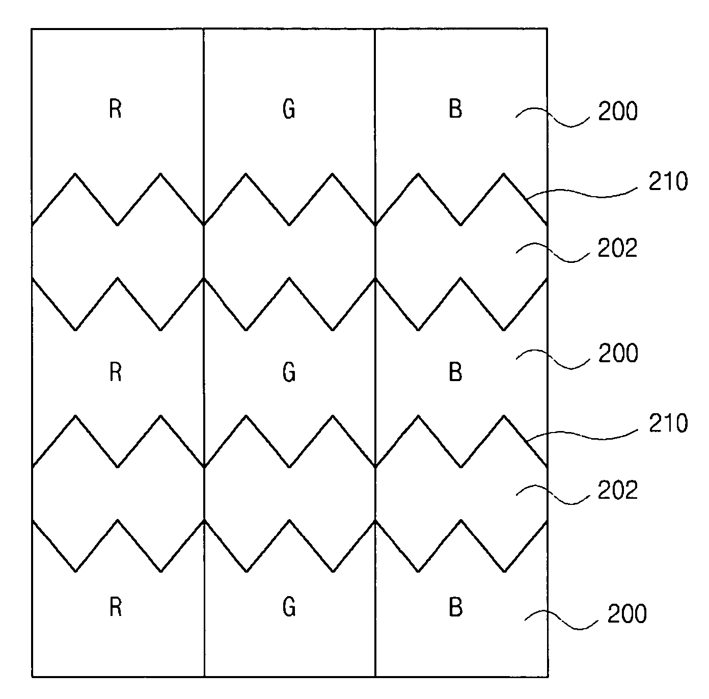
[0048]FIG. 5 is a schematic plan view of an exemplary color filter substrate having a shaped buffer layer pattern according to the present invention. In FIG. 5, transmissive regions 200 and reflective regions 202 may be alternately disposed along up-and-down directions in each of red (R), green (G), and blue (B) color regions. In addition, buffer patterns 210 may be disposed within the reflective regions 202, wherein each of the buffer patterns 210 may have a saw-tooth shape along sides of the buffer patterns 210. The saw-tooth shape may control flow of a viscous color photoresist when forming the R, G, and B color filters. Specifically, the saw-tooth shape may provide the color photoresist to be formed in the reflective regions 202 having a desired thickness, although the buffer patterns may have a high step.

[0049]FIG. 6 is a...


PUM


Abstract

A transflective LCD device includes first and second transparent substrates spaced apart from each other and having a reflective portion and a transmissive portion, an insulator on the first transparent substrate, a passivation layer on the insulator within the reflective portion, a reflector on the passivation layer, a transparent pixel electrode disposed over the insulator covering the reflector and the passivation layer, a buffer pattern disposed on a rear surface of the second substrate, the buffer pattern having a saw-tooth shape corresponding to the reflective portion, a color filter on the rear surface of the second substrate covering the buffer pattern, the color filter having a first thickness in the transmissive portion and a second thickness in the reflective portion, a transparent common electrode on a rear surface of the color filter, and a liquid crystal layer between the transparent pixel electrode and the transparent common electrode.

Description

[0001]The present invention claims the benefit of Korean Patent Application No. 2002-0088486, filed in Korea on Dec. 31, 2002, which is hereby incorporated by reference.BACKGROUND OF THE INVENTION[0002]1. Field of the Invention[0003]The present invention relates to a liquid crystal display device and a method of fabricating a liquid crystal display device, and more particularly, to a transflective liquid crystal display device having a dual thickness color filter and a method of fabricating the same.[0004]2. Description of Related Art[0005]Presently, liquid crystal display (LCD) devices having light weight, thin profiles, and low power consumption characteristics are commonly used in office automation equipment and video units. The LCD devices typically use a liquid crystal (LC) interposed between upper and lower substrates, and make use of optical anisotropy of the LC. Since molecules of the LC are thin and long, an alignment direction of the LC molecules can be controlled by appli...

Claims


Application Information

Patent Timeline
IPC IPC(8): G02F1/1333G02F1/1335G02F1/1339
CPCG02F1/133371G02F1/133516G02F1/133555G02F1/1335
Inventor JANG, SANG-MINJEONG, SEE-HWAKIM, MIN-JOO
Owner LG DISPLAY CO LTD
Why Eureka
Try Eureka