Unmanned plane lens

A camera lens and lens technology, applied in the field of optical lenses, can solve the problems of large distortion, poor sharpness and layering, and limited shooting frame of drone aerial photography lens, and achieve uniform color reproduction, good resistance to temperature changes, Good sharpness and layering effect

Active Publication Date: 2017-05-17
舜宇光学(中山)有限公司
View PDF12 Cites 15 Cited by
  • Summary
  • Abstract
  • Description
  • Claims
  • Application Information

AI Technical Summary

Problems solved by technology

[0002]With the wide application of UAV aerial photography, the general UAV aerial photography lens can only record images in a certain direction at the same time, and the shooting frame is very limited , and due to the low resolution of the lens itself when shooting, the captured image is not clear, the sharpness and layering are poor, and at the same time, the drone aerial photography lens is distorted greatly, resulting in image deformation, and there are also disadvantages such as large size
That is to say, the existing UAV aerial photography lenses have shortcomings such as small field of view, low resolution, poor sharpness and layering, large distortion, and large size.
[0003] Chinese Patent Document No. CN 105403982 A disclosed on March 16, 2016, a high-quality optical imaging lens for aerial photography of drones, and Chinese patent documents No. CN 105372789 A, disclosed on March 2, 2016, is a distortion-free, high-resolution, large-view UAV lens optical system, which has the disadvantage of large number of lenses and large volume.

Method used


Image

  • Unmanned plane lens
  • Unmanned plane lens
  • Unmanned plane lens

Examples


no. 1 example

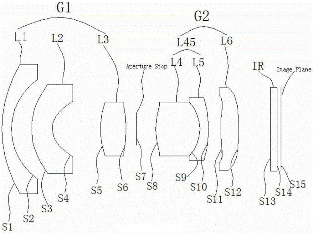
[0065] see Figure 1-Figure 8 and Figure 22 , the UAV lens, from the object side to the image side, includes a front lens group G1, an aperture stop Aperture Stop and a rear lens group G2, and the aperture stop is located in the middle of the lens, wherein the front lens group G1 includes a lens from the object The first lens L1 with a negative focal length, the second lens L2 with a negative focal length, and the third lens L3 with a positive focal length are arranged in sequence from side to image side. Each lens in the front lens group G1 has a convex surface facing the object side. The lens L1 and the second lens L2 are concave on the side facing the image surface, and the third lens L3 is convex on the side facing the image surface; the rear lens group G2 includes a fourth lens L4 with a positive focal length arranged sequentially from the object side to the image side , the fifth lens L5 with a negative focal length, and the sixth lens L6 with a positive focal length. ...

no. 2 example

[0104] see Figure 9-Figure 15 and Figure 23 , in this embodiment, when the working object distance WD=1m, the total focal length of the drone lens f=3.5mm, the aperture F#=2.85, the full field of view FOV=100°, the total lens length of the drone lens TL=25.1 mm,

[0105]

[0106]

[0107]

[0108] K A B C D E S3 1.7214 4.47E+03 -3.24E-04 2.11E-05 -9.68E-07 1.64E-08 S4 -0.6078 1.09E-02 -7.73E-04 1.46E-04 -2.11E-05 9.26E-05 S11 -9.575 -1.22E-04 -1.43E-04 -1.86E-06 2.44E-06 -1.36E-07 S12 -5.53E+10 2.10E-04 -2.63E-04 -3.57E-06 9.65E-07 -4.95E-08

[0109] n1+ln(v1) n2+v2 / 40.5 n3+v3 / 40.5 n6+v6 / 40.5 n5+ln(v5) 5.51 2.8 2.9 3.17 4.79

[0110] D1 / TL f / TL (D1+D2) / TL T1 / T2 T2 / T6 n4 / f4+0.05*v4 n5 / f5-0.045*v5 0.05 0.14 0.24 0.68 1.38 4.75 -1.06

[0111]

[0112]

[0113]In the above tables, n is the refractive index, R is the radius of curvature, ...

no. 3 example

[0116] see Figure 16-Figure 21 and Figure 24 , in this embodiment, when the working object distance WD=1m, the total focal length of the drone lens f=3.37mm, the aperture F#=2.82, FOV=100°, TL=25.1mm,

[0117]

[0118]

[0119] f1 / f2 f2 / f6 f1 / f6 fg1 / fg2 3.29 -0.59 -1.95 1.18

[0120]

[0121] K A B C D E S3 -0.3 2.51E-03 -3.17E-04 1.92E-05 -8.32E-07 1.61E-08 S4 -0.52 5.59E-03 -1.42E-03 1.42E-03 -1.99E-05 9.26E-07 S11 -16 1.80E-04 -3.24E-04 -1.14E-05 1.95E-06 -1.36E-07 S12 13 1.37E-03 -4.11E-04 5.49E-06 7.27E-07 -4.95E-08

[0122] n1+ln(v1) n2+v2 / 40.5 n3+v3 / 40.5 n6+v6 / 40.5 n5+ln(v5) 5.51 2.98 2.9 2.98 4.79

[0123] D1 / TL f / TL (D1+D2) / TL T1 / T2 T2 / T6 n4 / f4+0.05*v4 n5 / f5-0.045*v5 0.04 0.13 0.25 0.66 1.2 4.74 -1.11

[0124]

[0125]

[0126] The following is to list in the first embodiment to the third embodimen...


PUM


Abstract

The invention discloses an unmanned plane lens, and the lens sequentially comprises a front lens group, an aperture diaphragm and a rear lens group from the object space to the image space. The aperture diaphragm is located at the central part of the lens. The front lens group comprises a first lens with the negative focal length, a second lens with the negative focal length and a third lens with the positive focal length, wherein the first, second and third lenses are sequentially arranged from the object space to the image space. One surface, facing the object space, of each of the first, second and third lenses in the front lens group is a convex surface, and the surfaces, facing the image space, of the first and second lenses are concave surfaces. One surface, facing the image space, of the third lens is a convex surface. The rear lens group comprises a fourth lens with the positive focal length, a fifth lens with the negative focal length and a sixth lens with the positive focal length, wherein the fourth lens, the fifth lens and the sixth lens are sequentially arranged from the object space to the image space. One surface, facing the image space, of each lens of the rear lens group is a convex lens. The surfaces, facing the object space, of the fourth and sixth lenses are convex surfaces, and one surface, facing the object space, of the fifth lens is a concave surface. The lens provided by the invention is low in distortion, is big in view angle, is high in resolution, and is strong in capability of resisting the environment temperature changes.

Description

technical field [0001] The invention relates to an optical lens, in particular to an optical imaging lens for aerial photography of a drone. Background technique [0002] With the wide application of UAV aerial photography, the general UAV aerial photography lens can only record images in one direction at the same time, and the shooting frame is very limited, and the resolution of the lens itself is not high when shooting. It is not clear, the sharpness and layering are poor, and at the same time, the drone's aerial lens is distorted, resulting in image distortion, and there are also shortcomings such as large size. That is to say, the existing UAV aerial photography lenses have shortcomings such as small field of view, low resolution, poor sharpness and layering, large distortion, and large size. [0003] Chinese Patent Document No. CN 105403982 A disclosed on March 16, 2016 a high-quality optical imaging lens for unmanned aerial photography, and a Chinese Patent Document ...

Claims


Application Information

Patent Timeline
Patent Type & Authority Applications(China)
IPC IPC(8): G02B13/00G02B13/06
CPCG02B13/0045G02B13/06
Inventor 周静付湘发高屹东梁伟朝白兴安蓝岚张鸿佳
Owner 舜宇光学(中山)有限公司
Why Eureka
Try Eureka