
Accuracy analyzing apparatus for machine tool

a technology of accurate analysis and machine tools, applied in the direction of manufacturing tools, instruments, television systems, etc., can solve the problems of machining errors, lower efficiency, and higher cost, and achieve the effect of reducing costs and efficiently achieving the analysis of the accuracy of the machine tool

Inactive Publication Date: 2006-10-10
DMG MORI SEIKI CO LTD +1
View PDF3 Cites 12 Cited by
  • Summary
  • Abstract
  • Description
  • Claims
  • Application Information

AI Technical Summary

Benefits of technology

[0013]Since the light beam emitted from the light projecting means has a round cross section, a two-dimensional density image obtained by the imaging means includes a round image portion having a lower density level. The analyzing means binarizes the data of the two-dimensional density image obtained by the imaging means on the basis of a predetermined threshold level to extract the image portion corresponding to the emitted light beam, and analyzes the extracted binary image portion to analyze the accuracies of the machine tool. The light projecting means is preferably a laser oscillator which emits a laser beam, because the laser beam is excellent in linearity and convergence.
[0015]The accuracy analyzing apparatus according to the present invention is adapted to directly measure the displacement of the spindle and, therefore, capable of highly accurately analyzing the (thermal) displacement of the spindle and correspondingly making a correction for the (thermal) displacement with a higher level of accuracy.
[0020]In the aforesaid arrangements, the light receiving surfaces of the respective light receiving sections of the imaging means are disposed along the spindle axis (first axis). Therefore, the thermal displacement of the spindle described above can also be measured with these arrangements. In accordance with the present invention, the accuracies of the machine tool including the thermal displacement of the spindle and the perpendicularity of the spindle axis can be analyzed by the single accuracy analyzing apparatus. Thus, the analysis of the accuracies of the machine tool can efficiently be achieved at lower costs.
[0021]In any of the aforesaid arrangements, the accuracy analyzing apparatus may further comprise a transport device for moving at least the light receiving section of the imaging means between a light receiving position (imaging position) at which the light beam from the light projecting means is received and a stand-by position apart from the light receiving position. With this arrangement, the light receiving section is retracted at the stand-by position during a machining operation of the machine tool and, as required for the accuracy analysis, the light receiving section is positioned at the imaging position for the analysis. Thus, the analysis can be performed whenever necessary, and proper measures can be taken according to the results of the analysis. Therefore, the machine tool can be maintained in good conditions for a long period of time.

Problems solved by technology

When the spindle is rotated, bearings rotatably holding the spindle generate heat due to rolling of rolling elements thereof, so that the spindle is liable to be displaced (or extended) along the spindle axis by the generated heat thereby to cause a machining error.
However, the analysis of the perpendicularity of the spindle axis and the estimation of the thermal displacement amount of the spindle cannot be achieved by a single apparatus as can be understood from the above description.
This leads to lower efficiency and higher costs.
Since the thermal displacement of the spindle is estimated on the basis of the temperature measured around the spindle but not the temperature of the spindle itself, the estimation of the thermal displacement amount is not always accurate.

Method used


Image

  • Accuracy analyzing apparatus for machine tool
  • Accuracy analyzing apparatus for machine tool
  • Accuracy analyzing apparatus for machine tool

Examples


Embodiment Construction

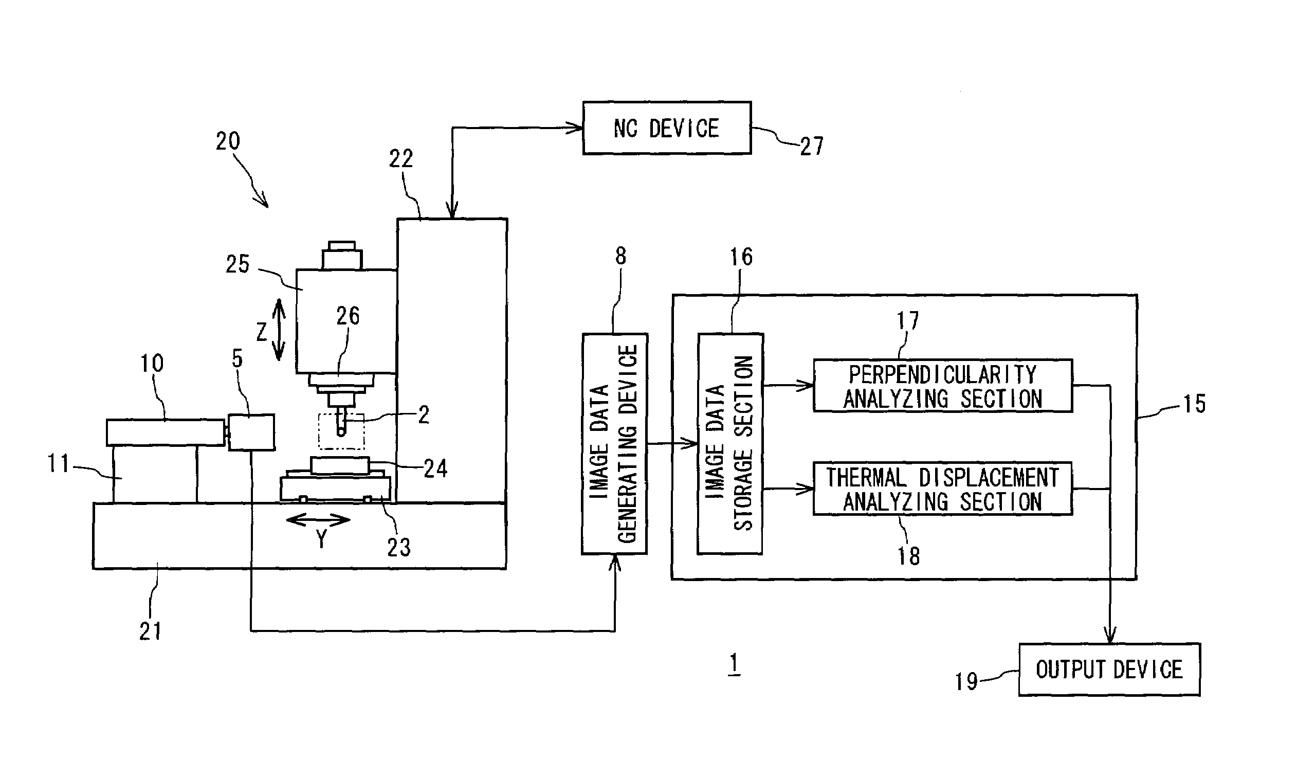
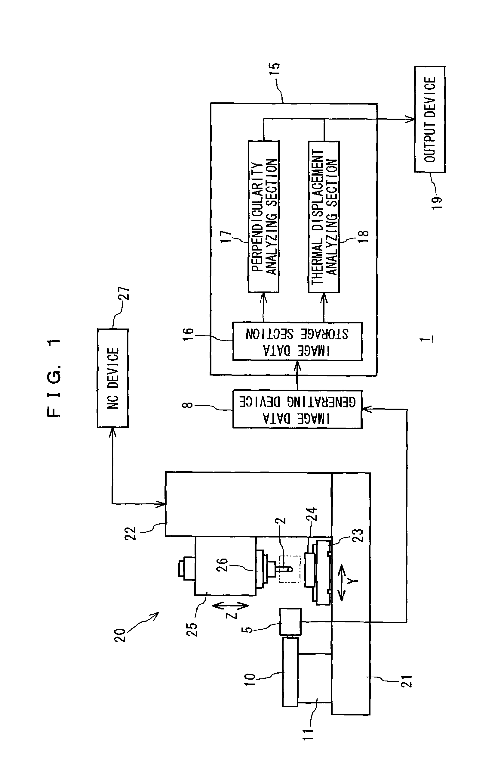
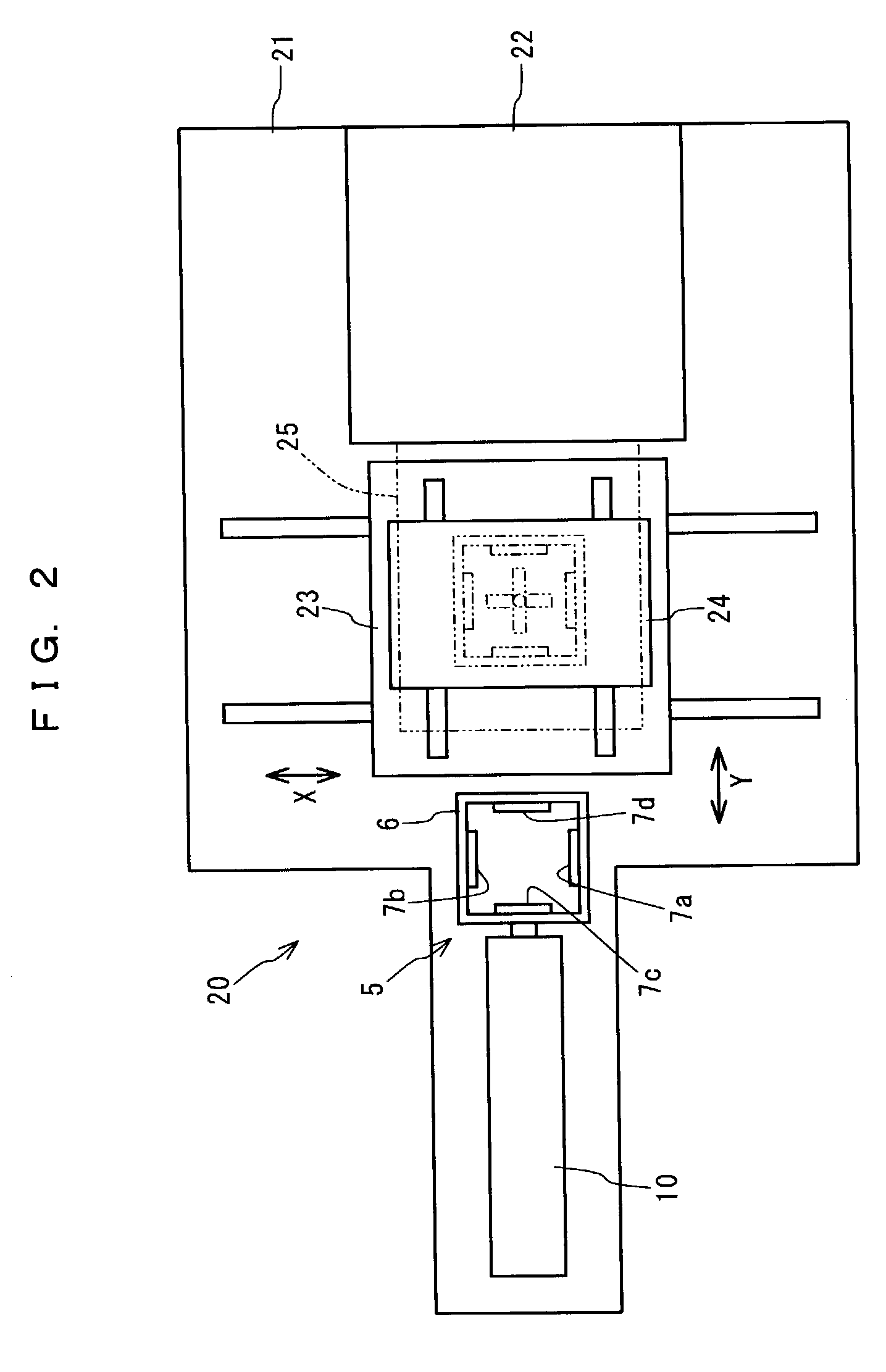
[0030]One preferred embodiment of the present invention will hereinafter be described with reference to the attached drawings. FIG. 1 is a block diagram illustrating the schematic construction of an accuracy analyzing apparatus according to the embodiment of the present invention, and FIG. 2 is a plan view of mechanical portions shown in FIG. 1.

[0031]As shown in FIGS. 1 and 2, the accuracy analyzing apparatus 1 according to this embodiment includes a laser oscillator 2 attached to a spindle 26 of a machine tool 20, a light receiving device 5 for receiving a laser beam emitted from the laser oscillator 2, an image data generating device 8 for generating two-dimensional image data on the basis of a signal outputted from the light receiving device 5, a transport device 10 for moving the light receiving device 5 between a light receiving position (indicated by a chain double-dashed line immediately below the spindle 26 in FIG. 2) defined between the spindle 26 and a table 24 and a stand...


PUM


Abstract

The present invention relates to an accuracy analyzing apparatus which is capable of efficiently analyzing accuracies of a machine tool including the perpendicularity of a spindle axis and the thermal displacement of a spindle with a higher level of accuracy at lower costs. The accuracy analyzing apparatus (1) comprises a laser oscillator (2) attached to the spindle (26) for emitting a laser beam having a light axis perpendicular to the spindle axis, an imaging device (5, 8) having a light receiving section (5) disposed in the vicinity of the laser oscillator (2) for receiving the laser beam from the laser oscillator (2) by the light receiving section (5) and generating two-dimensional image data, and an analyzer (15) for analyzing the accuracies of the machine tool (20) on the basis of the generated image data.

Description

BACKGROUND OF THE INVENTION[0001]1. Field of the Invention[0002]The present invention relates to an accuracy analyzing apparatus for a machine tool having a feed mechanism for relatively moving a table and a spindle along orthogonal three axes including a first axis extending along a spindle axis and second and third axes perpendicular to each other and perpendicular to the first axis, the accuracy analyzing apparatus being adapted to analyze the perpendicularity of a spindle axis with respect to the second axis and / or the third axis and the thermal displacement of the spindle.[0003]2. Description of the Prior Art[0004]The perpendicularity of a spindle axis directly affects the machining accuracy and, therefore, is usually checked and adjusted to satisfy a predetermined reference value before being shipped from a machine tool maker to a user.[0005]A conventional method for checking the perpendicularity is as follows. A straightedge is attached to a table to be fed by a feed mechanis...

Claims


Application Information

Patent Timeline
IPC IPC(8): G06K9/00B23Q17/22B23Q17/24G01B11/00G01B11/26G01B11/27
CPCB23Q17/22B23Q17/24G01B11/00G01B11/27
Inventor FUJISHIMA, MAKOTO
Owner DMG MORI SEIKI CO LTD
Learn More