
Connection verification for optical switches

a technology of optical switches and connection verification, applied in the field of optical switches, can solve the problems of human error, severe negative impact on service quality, and the probability with which errors can be made when switching individual optical signals

Inactive Publication Date: 2006-10-10
RPX CLEARINGHOUSE
View PDF4 Cites 6 Cited by
  • Summary
  • Abstract
  • Description
  • Claims
  • Application Information

AI Technical Summary

Benefits of technology

"The present invention provides a system for non-intrusively verifying the connections made through an optical switch. This is done by analyzing the low-frequency content of the input and switched signals and comparing them against a connection map to determine if the switch has operated correctly and identify any mis-connections. The invention can also be used as a method for validating the connections made through a switching unit and as a computer-readable media for performing the method. The technical effect of the invention is to provide a reliable and efficient means for ensuring the proper operation and consistency of optical switches."

Problems solved by technology

As the density of emerging high-capacity WDM systems increases, so too does the probability with which errors can be made when switching individual optical signals.
Examples of what may cause an erroneous or lost connection include stuck or failed switch elements in the switching core of an optical switch, hardware or software failures causing incorrect switch path instructions to be received by the switching core from a switch controller, and human error (e.g., a mis-connected fiber interconnect into or between bays of switching equipment).
Given the high line rates currently used in WDM networks and the even higher line rates contemplated for use in the foreseeable future, it is clear that erroneous or lost connections can and will have a very severe negative impact on quality of service by causing the loss of large amounts of information.
However, these requirements have yet to be met by existing connection verification techniques.

Method used


Image

  • Connection verification for optical switches
  • Connection verification for optical switches
  • Connection verification for optical switches

Examples


Embodiment Construction

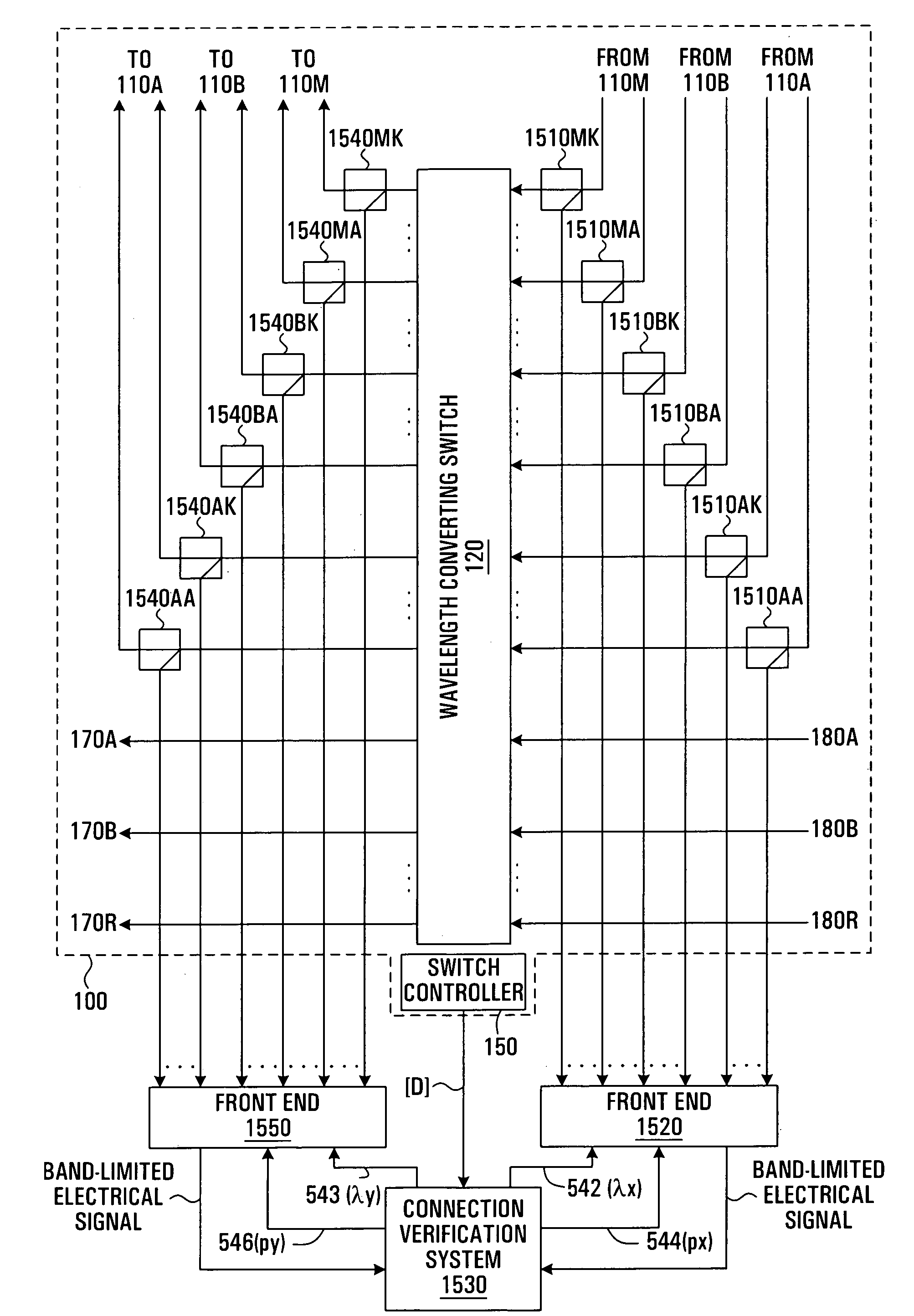
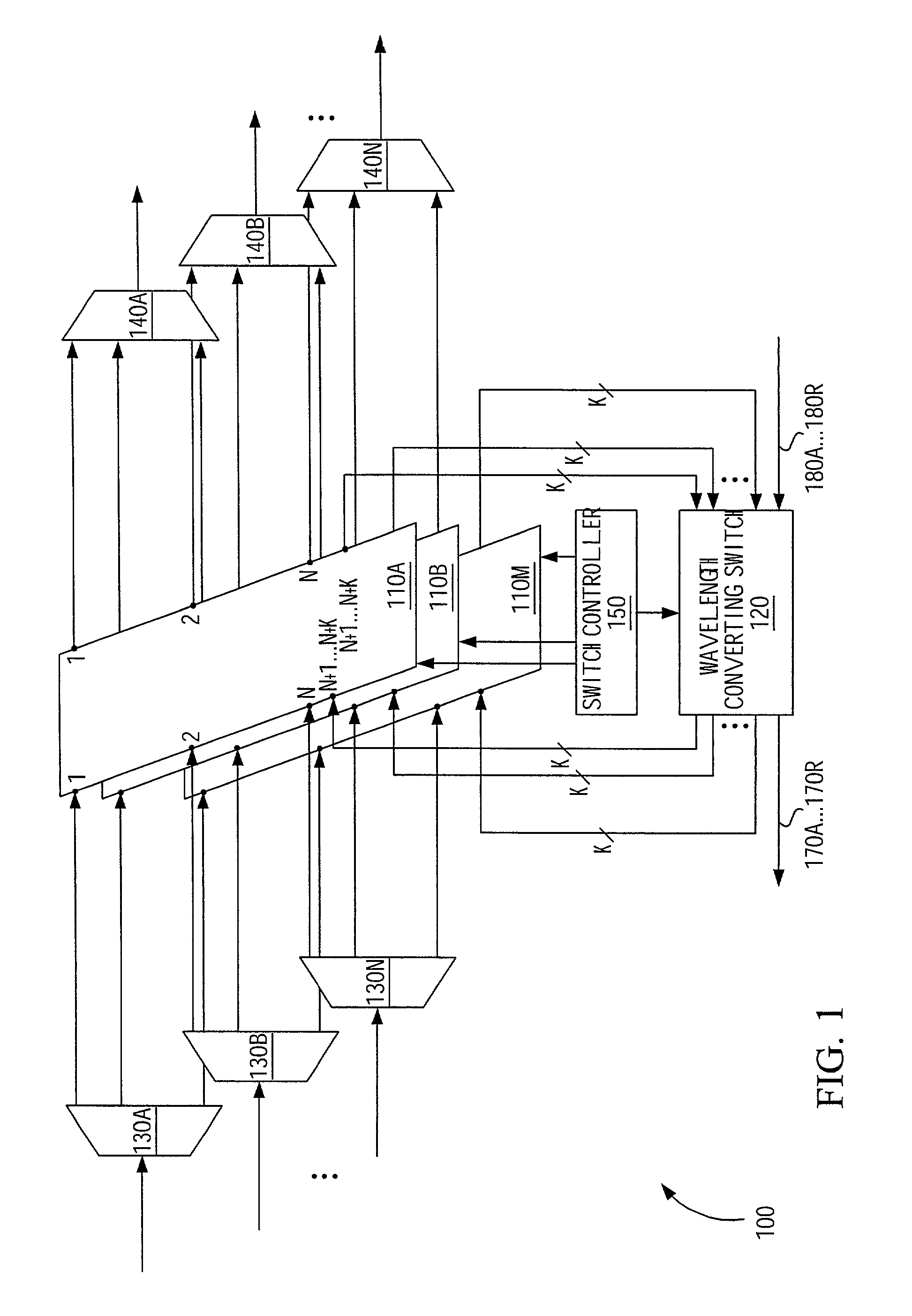
[0032]As will be described in further detail herein below, the connection verification system of the present invention correlates the low-frequency content of a set of input single-carrier optical signals with the low-frequency content of a set of switched single-carrier optical signals. For best performance of the connection verification system, the low-frequency content (representing the first, say, 10–100 MHz of signal spectrum, depending on the design) of the various input signals arriving at the switch should be sufficiently unique and / or randomized so that the cross-correlation of the low-frequency content of any pair of distinct input signals is relatively weak compared to each signal's auto-correlation. This condition is met for most forms of scrambled binary information transmission including those commonly in use with existing fiber systems, such as SONET, SDH, PDH, Gigabit Ethernet, 10GE, as well as direct IP-over-wavelength, and wavelength-wrapper-encapsulated signals.

[0...


PUM


Abstract

A connection verification system that provides substantially non-intrusive connection verification for an optical switch, achieved by correlating the low-frequency contents of the input and switched signals. The results of the correlation process are compared against a connection map to determine whether the switch has operated correctly and to identify, if possible, which mis-connections have taken place. The system includes a selection unit for controllably admitting individual ones of the input signals and individual ones of the switched signals and a verification unit connected to the selection unit, for controlling operation of the selection unit as a function of a connection map and performing relative-delay-dependent signal processing operations on the signals admitted by the selection unit so as to identify connections established through the switching unit and determine their consistency with the connection map. The relative-delay-dependent signal processing operations may be based on correlation or anti-correlation, depending on the operational requirements of the invention.

Description

FIELD OF THE INVENTION[0001]The present invention relates generally to optical switches and, more particularly, to systems for verifying connections through such switches.BACKGROUND OF THE INVENTION[0002]As the density of emerging high-capacity WDM systems increases, so too does the probability with which errors can be made when switching individual optical signals. Examples of what may cause an erroneous or lost connection include stuck or failed switch elements in the switching core of an optical switch, hardware or software failures causing incorrect switch path instructions to be received by the switching core from a switch controller, and human error (e.g., a mis-connected fiber interconnect into or between bays of switching equipment).[0003]Given the high line rates currently used in WDM networks and the even higher line rates contemplated for use in the foreseeable future, it is clear that erroneous or lost connections can and will have a very severe negative impact on qualit...

Claims


Application Information

Patent Timeline
Patent Type & Authority Patents(United States)
IPC IPC(8): H04B10/08H04J14/02H04Q11/00
CPCH04J14/0212H04Q11/0005H04J14/02H04J14/021H04Q2011/0011H04Q2011/0016H04Q2011/0024H04Q2011/0039H04Q2011/0043H04Q2011/0083
Inventor GRAVES, ALAN F.BRYANT, ANDREW J.VAN SCHYNDEL, ANDRE J.GRUBER, JOHN G.
Owner RPX CLEARINGHOUSE
Learn More