
High-accuracy continuous duty-cycle correction circuit

a duty-cycle correction and high-accuracy technology, applied in the field of processing signals, can solve problems such as phase-path failure, core clock duty-cycle distortion, and increase the sensitivity of the maximum operating frequency of the cpu

Inactive Publication Date: 2006-10-10
INTEL CORP
View PDF7 Cites 13 Cited by
  • Summary
  • Abstract
  • Description
  • Claims
  • Application Information

AI Technical Summary

Benefits of technology

The present invention relates to a system and method for processing signals, and more particularly to a system and method for performing duty-cycle correction of clock and other frequency signals. The technical effect of the invention is to provide a more efficient and effective solution for correcting duty-cycle distortion in synchronous chips, which is caused by process variations and changes in voltage supply level. The invention uses a duty-cycle correction loop that includes a duty-cycle correction circuit and a global clock network. The duty-cycle correction circuit generates a corrected output clock signal from an input clock signal by continuously monitoring the clock signal and adjusting the control voltage to correct any distortion. The global clock network distributes the corrected clock signal to other circuits. The invention ensures that the duty cycle of the core clock signal is maintained at a predetermined value, which is important for optimal performance. The invention is efficient and effective in measuring and correcting duty-cycle distortion, and can be used in high-performance CPUs.

Problems solved by technology

As a result, if one of the clock phases in a synchronous chip is reduced, data may be sampled earlier than expected and this may lead to phase-path failure.
As presently implemented, this design has a number of drawbacks, not the least of which include increasing the sensitivity of the maximum operating frequency of the CPU relative to duty-cycle distortion of a core clock signal.
In fact, core clock duty-cycle distortion is one of the main factors that limits the maximum frequency of the CPU.
This approach is undesirable for at least two reasons.
First, valuable tester time is wasted which makes the procedure inefficient.
Second, testing is performed at only one voltage point, which tends to diminish the effectiveness of the overall process.

Method used


Image

  • High-accuracy continuous duty-cycle correction circuit
  • High-accuracy continuous duty-cycle correction circuit
  • High-accuracy continuous duty-cycle correction circuit

Examples


Embodiment Construction

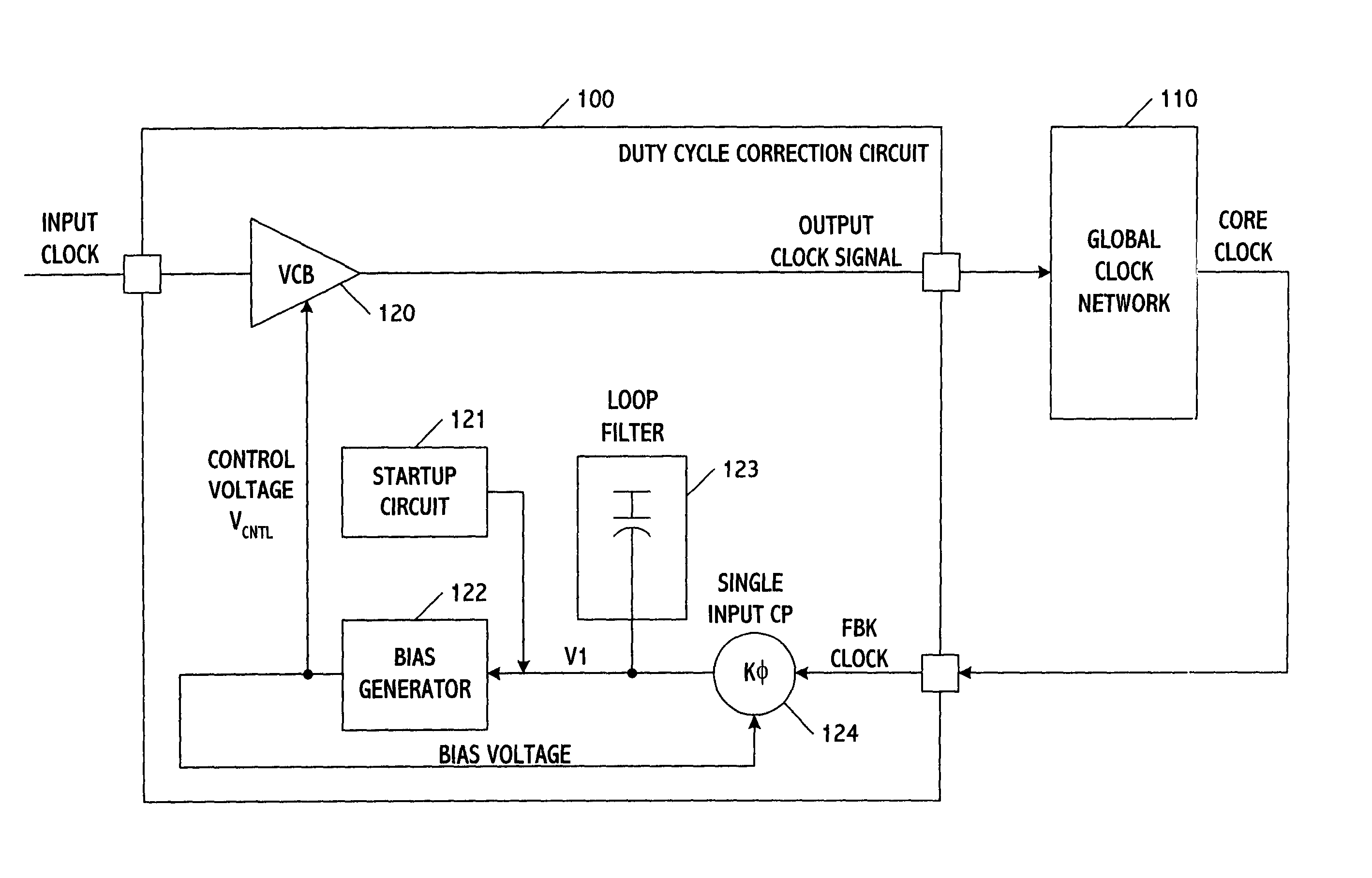
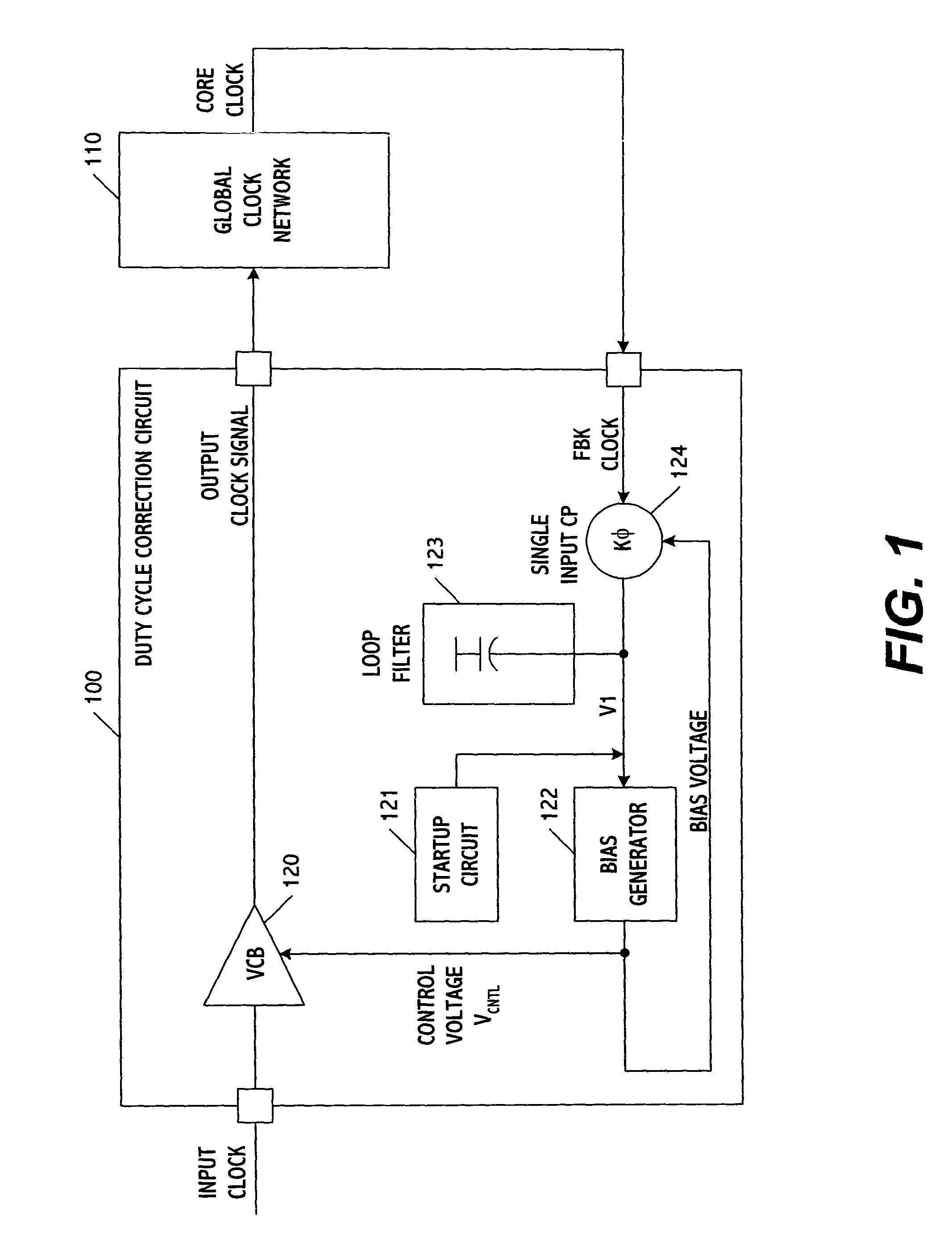
[0016]FIG. 1 shows a duty-cycle correction loop according to one embodiment of the present invention. The loop includes a duty-cycle correction circuit 100 and a global clock network 110. The duty-cycle correction circuit includes a voltage-controlled buffer (VCB) 120, a startup circuit 121, and a bias generator 122 as well as a loop filter 123 and a single-input charge pump (CP) 124. Using these elements, the duty-cycle correction circuit generates a corrected output clock signal from an input clock signal.

[0017]The global clock network distributes the signal output from the correction circuit to other circuits. This may be accomplished using one or more buffers which control the timing and distribution of the correction circuit signal. The global clock network may therefore be considered a distribution network (i.e., one that takes the clock signal output from the correction circuit and merely distributes where needed), as opposed to one which changes the frequency of the clock si...


PUM

PropertyMeasurementUnit
clock frequencyaaaaaaaaaa
voltageaaaaaaaaaa

Abstract

A control circuit corrects duty-cycle distortion of clock signals accurately and with a fast and continuous response over a wide dynamic range. In one embodiment, the duty-cycle correction circuit includes a self-biased loop that corrects duty-cycle distortions to preferably less than + / −1%. The duty-cycle correction circuit also compensates for changes in a supply voltage. These corrections may take place on a continuous basis, not only during a testing period but also during normal operation of the host system driven by the clock signals.

Description

BACKGROUND OF THE INVENTION[0001]1. Field of the Invention[0002]The present invention relates to processing signals, and more particularly to a system and method for performing duty-cycle correction of clock and other frequency signals.[0003]2. Background of the Related Art[0004]Synchronous chips often use a latch design in which a logic path propagates in one phase (high or low) of a clock signal. In chips of this type, phase paths are influenced by duty-cycle distortion of the clock signal. This mainly occurs because of process variations and / or changes in the level of the voltage supply (e.g., changes in transistor characteristics with voltage supply level). As a result, if one of the clock phases in a synchronous chip is reduced, data may be sampled earlier than expected and this may lead to phase-path failure.[0005]To overcome this problem, the frequency of the clock signal can be reduced to a value that compensates for and thus restores the original phase duration. For example...

Claims


Application Information

Patent Timeline
Patent Type & Authority Patents(United States)
IPC IPC(8): G11B20/22G11B20/24G06F1/04G06K5/04G11B5/00G11B20/20H03K5/156
CPCG06F1/04H03K5/1565
Inventor FAYNEH, EYALKNOLL, ERNEST
Owner INTEL CORP
Learn More