Heat exchanger

a technology of heat exchanger and heat exchanger plate, which is applied in the direction of solar heat collectors with working fluids, stationary plate conduit assemblies, solar heat devices, etc., can solve the problems of reducing the heat conductivity of ferrous metals. , to achieve the effect of external pressure, and reducing the internal pressur

Inactive Publication Date: 2006-10-17
SC SUNPOWER CONCEPT ESTAB
View PDF9 Cites 22 Cited by
  • Summary
  • Abstract
  • Description
  • Claims
  • Application Information

AI Technical Summary

Benefits of technology

[0011]The use of heat exchangers comprising two independent metal sheets or one sheet lock-seamed together has the advantage that an endless web can be manufactured. The sheet-metal web can be shaped before being joined. One or both edges extending longitudinally of the web can be joined and closed in a conventional way, such as lock-seaming and soldering.
[0012]The sheet or sheets that form the walls to be joined are advantageously preshaped before being joined. A circular indentation at the points of the compression-molded connections has proved an advantageous deformation of the sheet. The indentation has a somewhat larger diameter than the compression-molded connection and defines the spacing of the two walls and therefore also defines the cross section of the flat heat exchanger through which a medium can flow. However, the indentation also reinforces the wall in the region of the compression-molded connections. Thanks to this reinforcement, the

Problems solved by technology

Since the heat transfer paths and the heat transfers between the sheet-metal faces and the pipe carrying the medium impair the capacity of a heat exchanger, many attempts have been made to put heat exchanger faces with the greatest possible surface area into direct contact with the media on both sides.
The problem in flat heat exchangers, which have a wall with the largest possible surface area in contact with the media on the inside and the outside but the smallest possible internal volume, is the pressure difference between the internal pressure

Method used


Image

  • Heat exchanger
  • Heat exchanger
  • Heat exchanger

Examples


Embodiment Construction

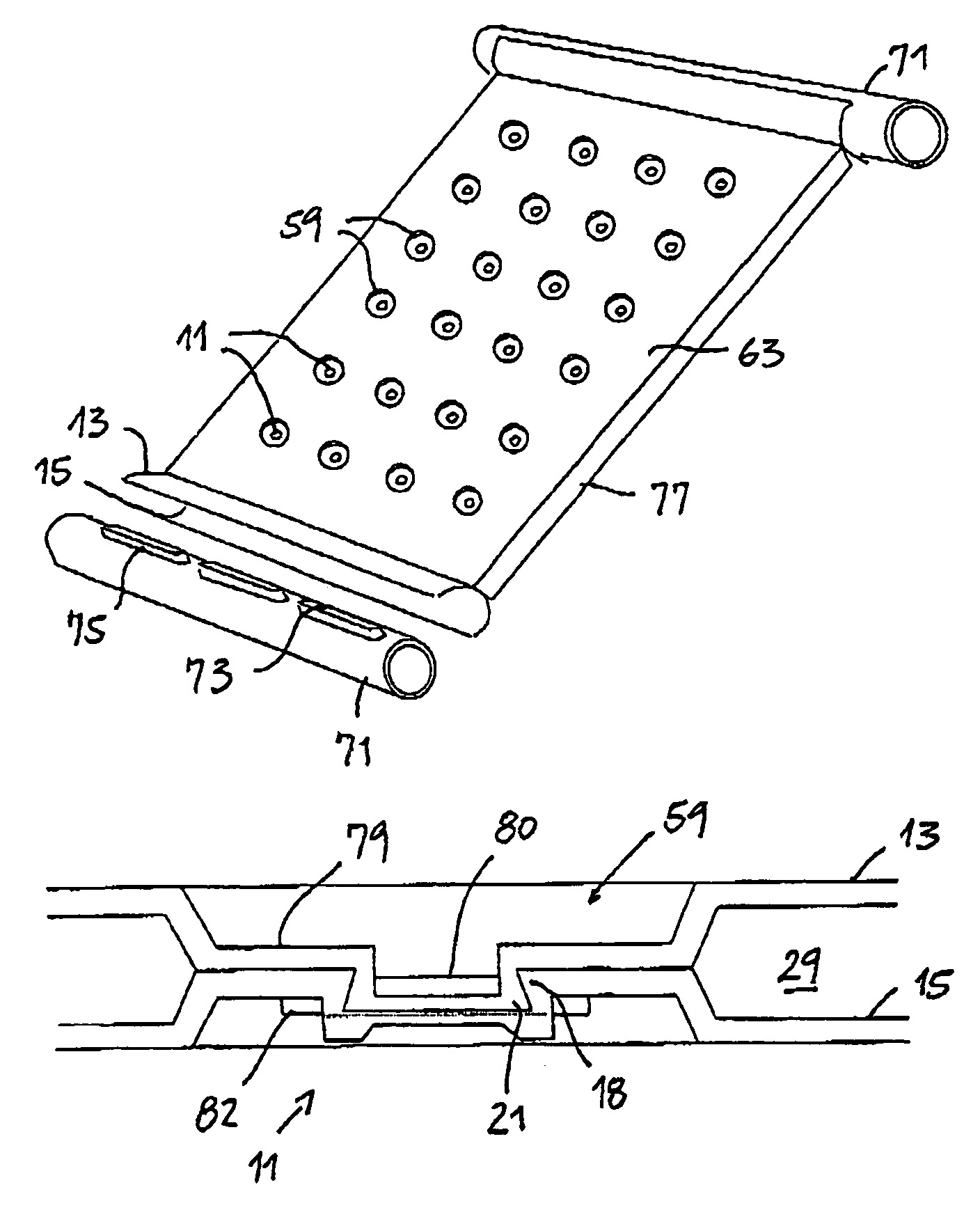
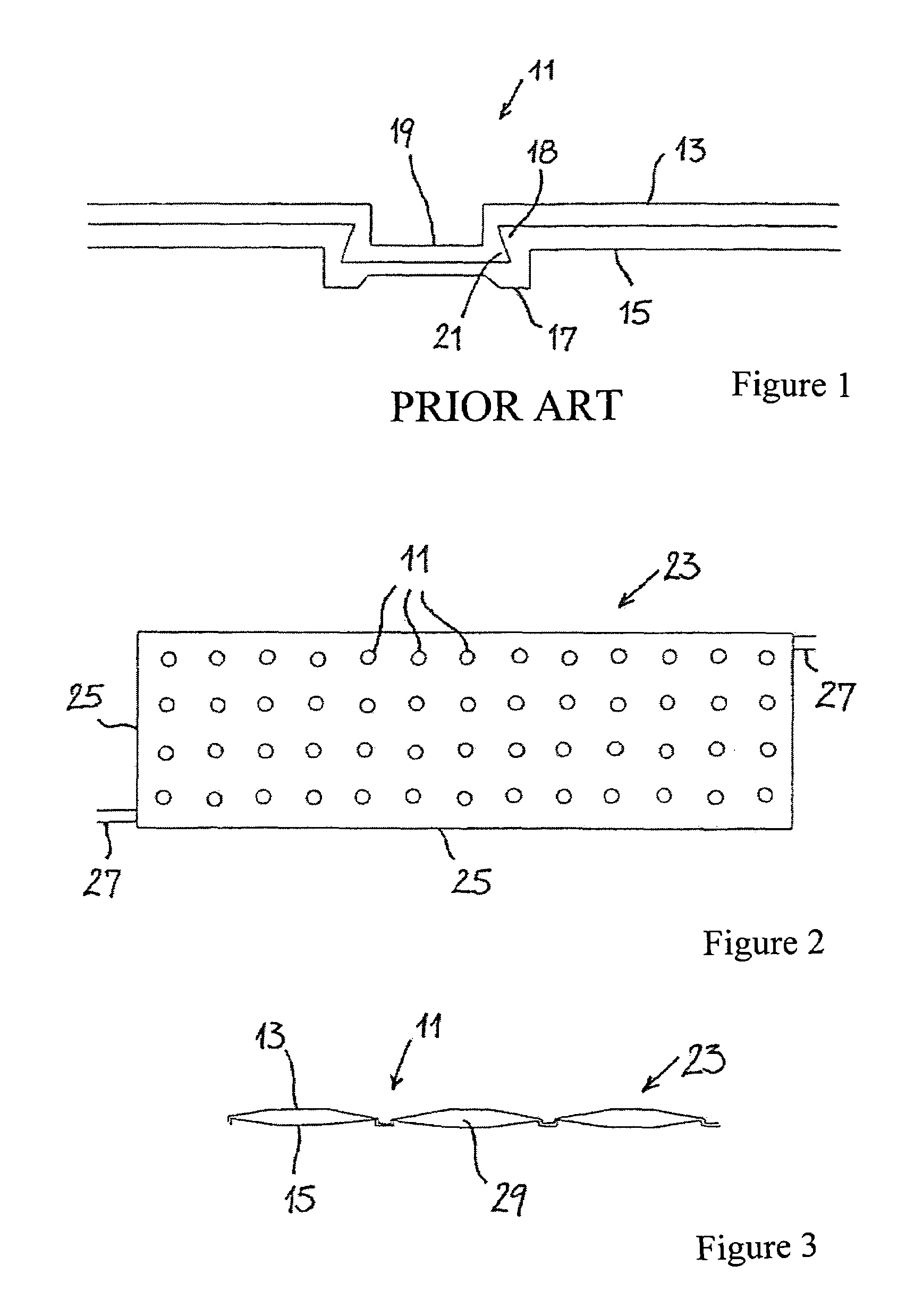
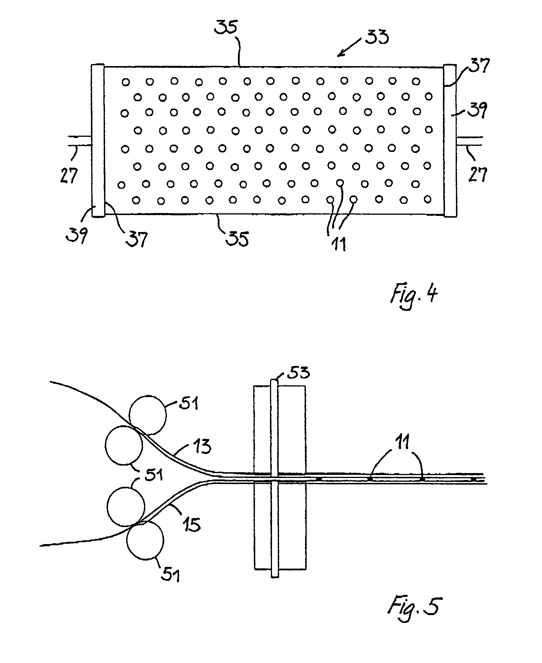
[0008]According to the invention, this is attained in that to fasten the walls to one another inside the surface between the edges of the heat exchanger, the walls are made to mesh with one another by deformation of the material. The meshing by positive engagement is accomplished merely by means of an upsetting-pressing operation, without injuring the wall or making a damaging change to the structure of the material. Subsequently both walls remain free of apertures or cracks, so that even loosening of the connecting point need not cause any leakage. Such denticulations can be made linearly on the order of profile sections, given a sufficient material thickness of the wall.

[0009]The material deformation is preferably done in punctate form. The term “punctate material deformation” is understood to mean that the material is deformed at an approximately circular place having a diameter of between 2 and 15 mm, and preferably between 3 and 8 mm, depending on the material thickness of the ...


PUM

PropertyMeasurementUnit
Thicknessaaaaaaaaaa
Thicknessaaaaaaaaaa
Lengthaaaaaaaaaa

Abstract

This invention relates to a heat exchanger which is produced by connecting two walls together at a plurality of points by compression molding and sealing the edges thereof.

Description

FIELD OF THE INVENTION[0001]The invention relates to a method for producing a heat exchanger with a flow-through chamber for a heat transfer medium, in which two walls are disposed opposite one another and joined to make a hollow body through which a medium can flow. The invention also relates to a heat exchanger with two walls, facing one another and joined together, and with a flow-through chamber between them for a heat transfer medium, and to the use of a method for punctate connection of two metal sheets resting over a large area on one another.PRIOR ART[0002]For pumping the medium, in heat exchangers in overpressure of approximately 1.5*105 Pa is used. Heat exchangers with a relatively high throughput must be capable of withstanding such an overpressure, or an even higher one. In powerful heat exchangers, pipes for carrying the medium are therefore often used, and laminations or sheet-metal faces are fastened to these pipes. Over the pipe surface but above all over these sheet...

Claims


Application Information

Patent Timeline
IPC IPC(8): B21D53/04F28F3/14B21D39/03F24S10/50F28D9/00
CPCB21D39/031B21D53/045F24J2/208F24J2/22F28D9/0031F28F3/14Y10T29/49366F28F2250/04F28F2275/14Y02E10/44F28F2225/04F24S10/55F24S10/506
Inventor ROTH, MAX
Owner SC SUNPOWER CONCEPT ESTAB
Why Eureka
Try Eureka