
Device for the control of an active element of an occupant retention system in a vehicle

a technology for occupant restraint systems and active elements, which is applied in the direction of pedestrian/occupant safety arrangements, instruments, tractors, etc., can solve the problems of slow and relatively expensive, difficult testing of mechanical safing sensors usually arranged in the control unit (ecu) of the restraint system, and inability to reliably identify safing concepts

Inactive Publication Date: 2006-10-17
CONTINENTAL AUTOMOTIVE GMBH
View PDF17 Cites 11 Cited by
  • Summary
  • Abstract
  • Description
  • Claims
  • Application Information

AI Technical Summary

Benefits of technology

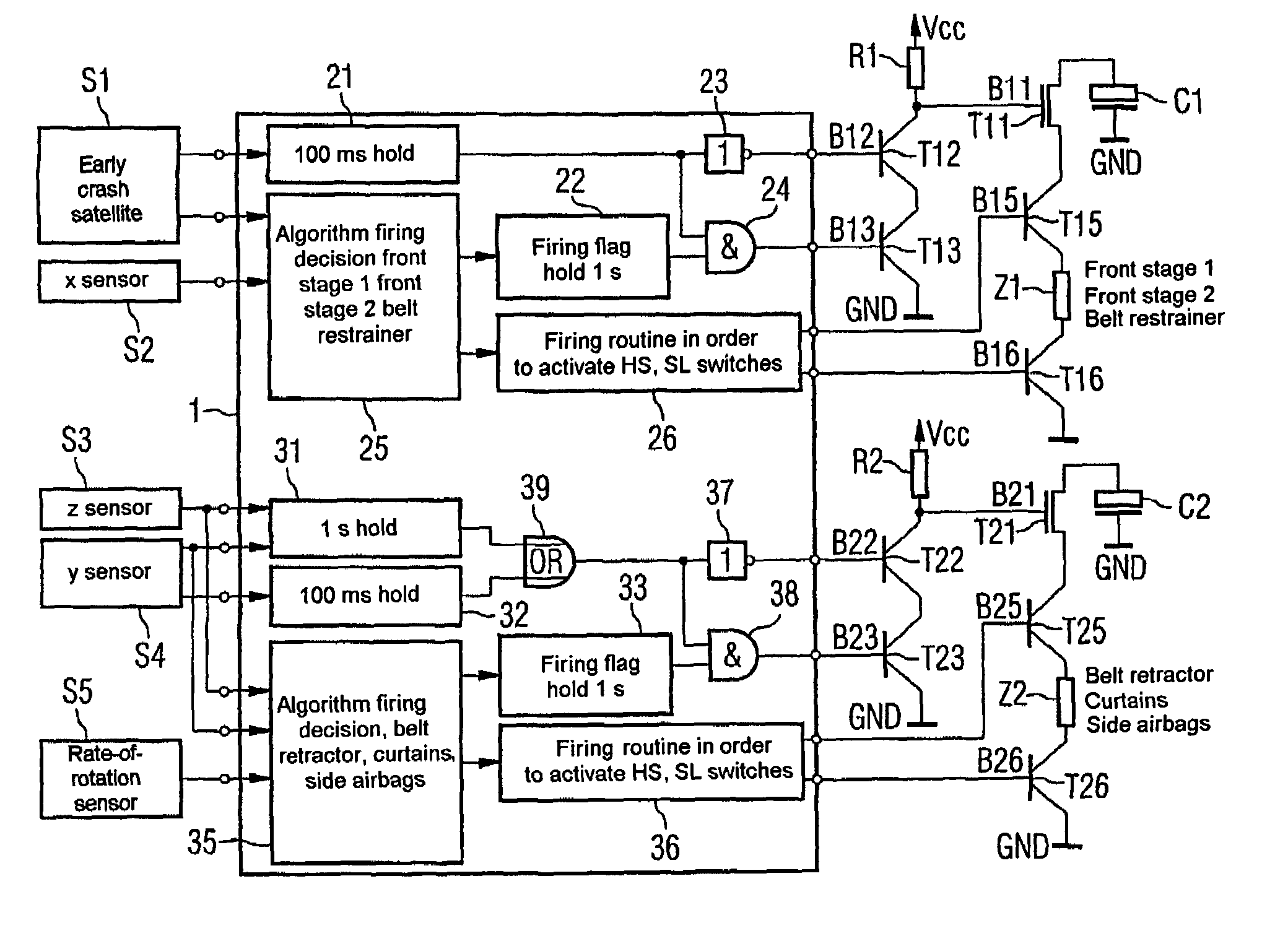
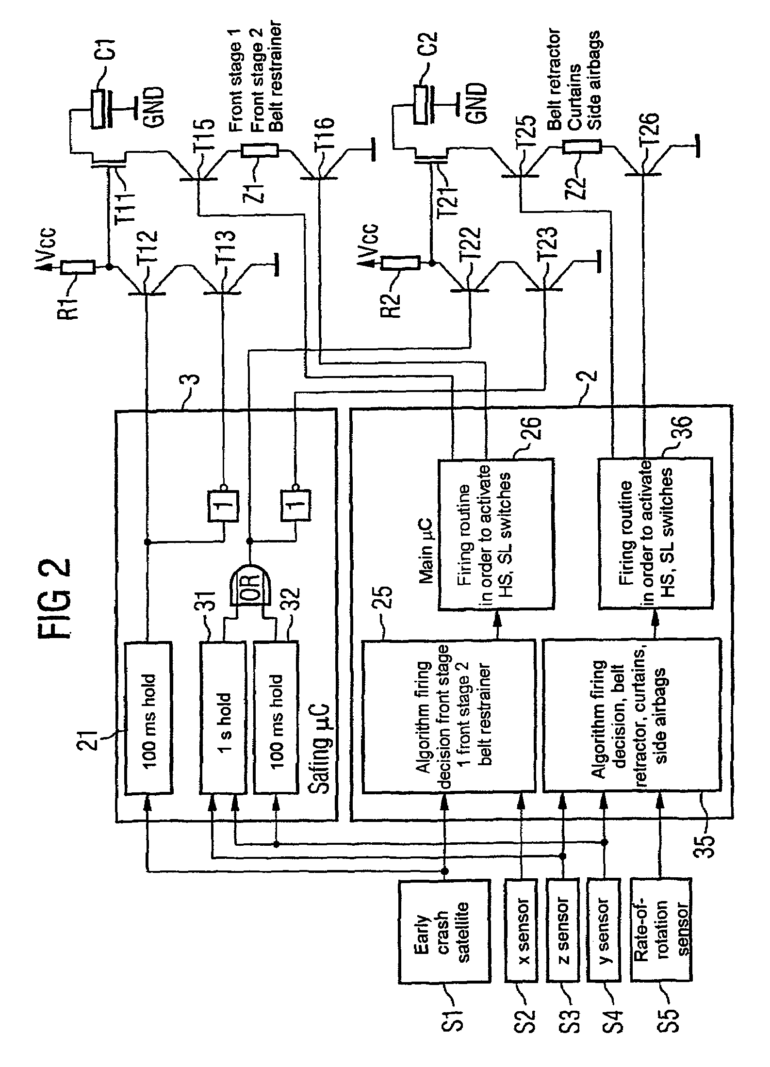
[0006]One advantage of the invention is to allow one safing sensor to be saved. To that end, the detection of a frontal impact with the aid of a safing sensor is shifted into the early crash satellite or sensor, which is preferably integrated in the front part of the vehicle, e.g. in the fender thereof and / or in the front engine compartment.
[0007]For the safing function in the identification of a side impact, the acceleration sensor in the Y direction, i.e. in the direction of the wheel axles transversely with respect to the vehicle direction, is simultaneously used as a safing sensor.
[0008]For the safing function in the identification of a rollover state, at least one of the acceleration sensors which act in the y direction and in the z direction is simultaneously used as a safing sensor.
[0009]In another embodiment, there are a plurality of participating sensors which simultaneously fulfill the function of safing sensors.
[0010]For the evaluation of the sensor signals, a control unit (ECU) with downstream, multistage safety switches, for example comprising a prestage with two transistors and a safety transistor connected downstream, is used to realize a safing concept.
[0011]A safety switch is additionally provided in the ignition path including the ignition element, the energy store and the ignition switches. Ignition of the ignition element occurs when both the ignition switch / switches and the safety switch turn on simultaneously. The safety transistor in the ignition path is driven by a prestage which enables the safety switch when a sufficiently high acceleration is present.

Problems solved by technology

The previous mechanical safing sensors usually arranged in the control unit (ECU) of the restraint system are difficult to test, slow and relatively expensive.
To date, there has not been a reliable safing concept for the identification of a rollover with subsequent triggering of side airbags, curtains, etc.

Method used


Image

  • Device for the control of an active element of an occupant retention system in a vehicle
  • Device for the control of an active element of an occupant retention system in a vehicle
  • Device for the control of an active element of an occupant retention system in a vehicle

Examples


Embodiment Construction

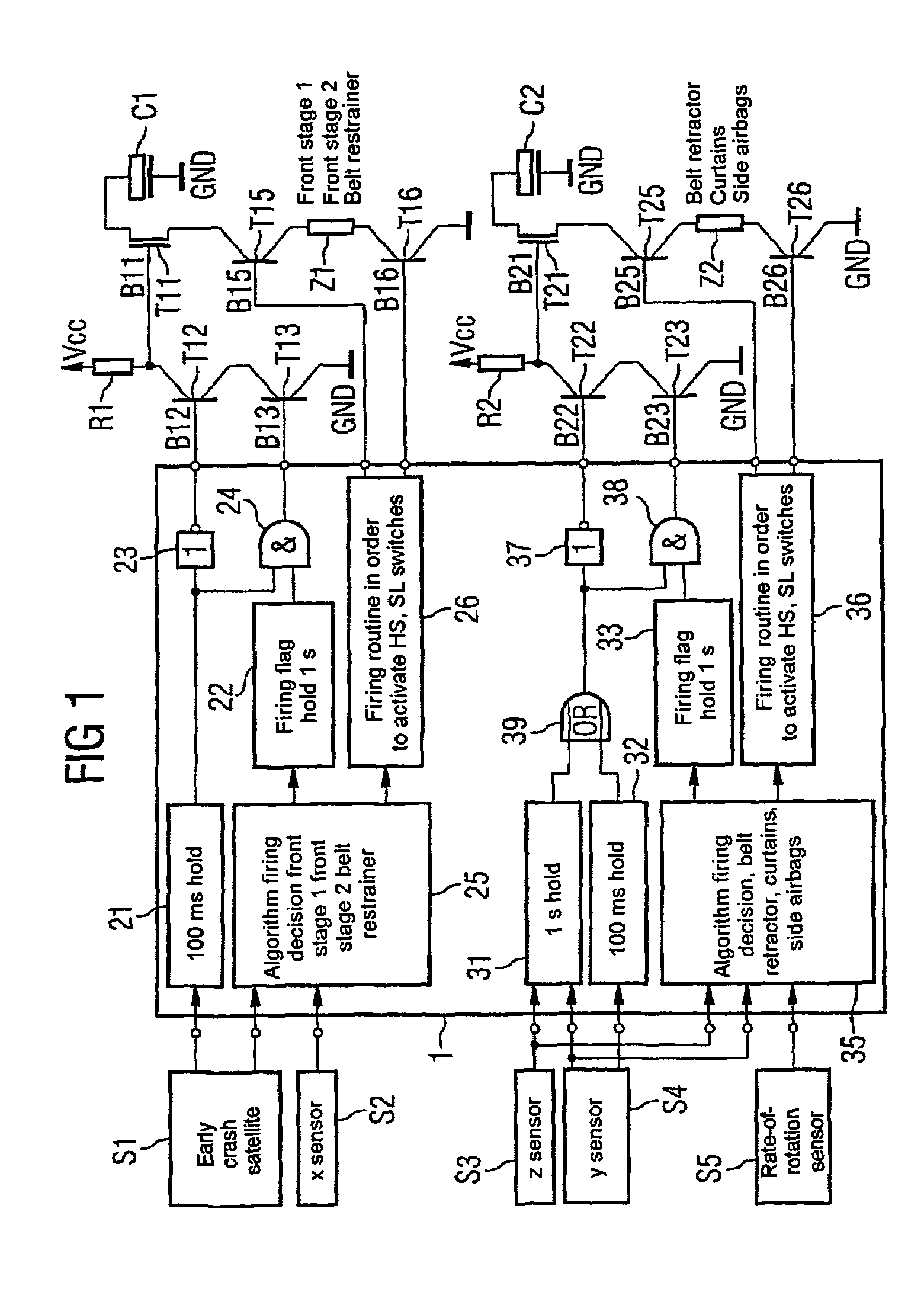
[0024]FIG. 1 shows a drive arrangement for an active element, designed as ignition elements Z1, Z2, for example, in which a controller 1 controls ignition parts with an active element depending on sensor signals. Furthermore, control unit 1 controls prestages R1, T12, T13 and R2, T22, T23, thereby ensuring that the active element Z1, Z2 can be activated or ignited when both the impact identification unit and the safing function have identified a sufficiently high acceleration.

[0025]FIG. 1 shows a plurality of sensors S1 to S5, whose sensor signals are fed to the controller 1. The sensor 1 is designed as an early crash satellite and is arranged in the front region of the vehicle, preferably in the region of the fender. As a result, a frontal impact is detected particularly early. The early crash satellite has an acceleration sensor which preferably detects movements in the direction of travel, i.e. in the X direction.

[0026]The sensor S2 is an acceleration sensor which senses movement...


PUM


Abstract

In order to produce a safing concept, an extra-safing-sensor in the control unit (ECU) is foregone and the safing function from one of the available acceleration or turn-rate sensors (S1 to S5) is replaced. Furthermore a pre-stage is connected to the firing element (Z1, Z2), before the existing firing path, which, depending upon the sensor signals as analysed by the controller unit (1), controls a safety switch (T11), in series with the firing switches and the firing element.

Description

CLAIM FOR PRIORITY[0001]This application claims priority to International Application No. PCT / DE01 / 01827 which was published in the German language on May 14, 2001.TECHNICAL FIELD OF THE INVENTION[0002]The invention relates to a device for driving an active element of an occupant restraint system of a vehicle.BACKGROUND OF THE INVENTION[0003]Conventional occupant restraint systems have a mechanical safing sensor incorporated in the central controller of the occupant restraint system. The previous mechanical safing sensors usually arranged in the control unit (ECU) of the restraint system are difficult to test, slow and relatively expensive.[0004]A safing concept with a safing function in the restraint system means that an undesirable triggering of the occupant restraint system in the event of a malfunction of the impact identification unit, which has the sensors and the controller of the occupant restraint system, is prevented. To date, this has only been realized for the identifica...

Claims


Application Information

Patent Timeline
IPC IPC(8): B60K28/12B60R21/00B60R21/01B60R21/013B60R21/0132B60R21/13B60R21/20B60R22/46
CPCB60R21/017B60R21/0173B60R21/0132B60R2021/01027B60R2021/01306B60R2021/01325B60R2021/01327B60R21/01B60R2021/01184
Inventor BAUMGARTNER, WALTERBRAUNER, NORBERTFOELL, ALBRECHT
Owner CONTINENTAL AUTOMOTIVE GMBH
Learn More