Flexible metal hose assembly and method of making the same

Active Publication Date: 2006-10-17
HOSE MASTER
View PDF16 Cites 4 Cited by
  • Summary
  • Abstract
  • Description
  • Claims
  • Application Information

AI Technical Summary

Benefits of technology

[0018]The present invention addresses a need for an improved hose assembly that includes a hose and a fitting where an inner surface at the interface between the hose and fitting is relatively smooth. The resulting hose assembly is able to carry a product without damaging the product.

Problems solved by technology

Welding is not recommended, however, for packed interlocked hose, as

Method used


Image

  • Flexible metal hose assembly and method of making the same
  • Flexible metal hose assembly and method of making the same
  • Flexible metal hose assembly and method of making the same

Examples


Embodiment Construction

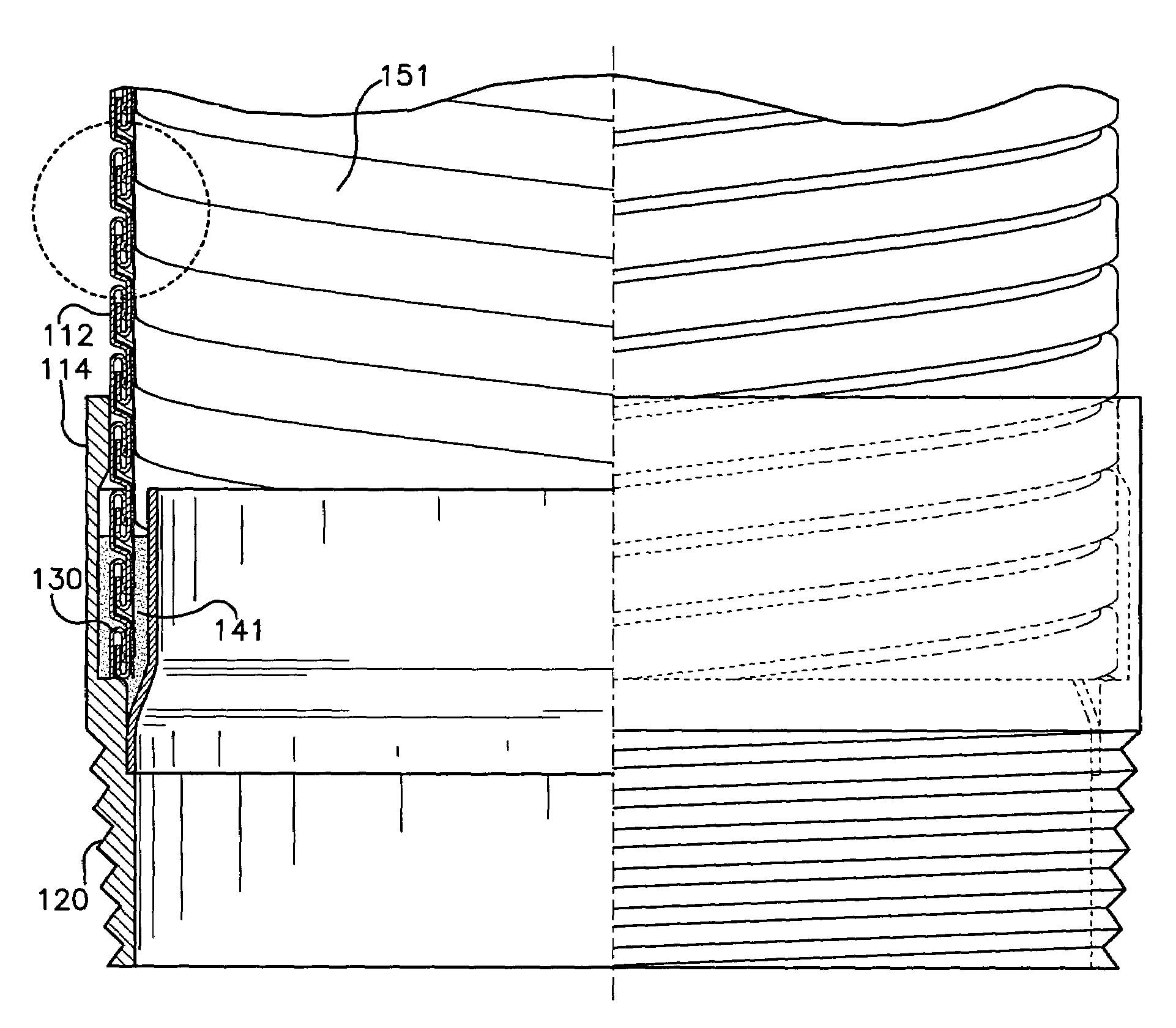
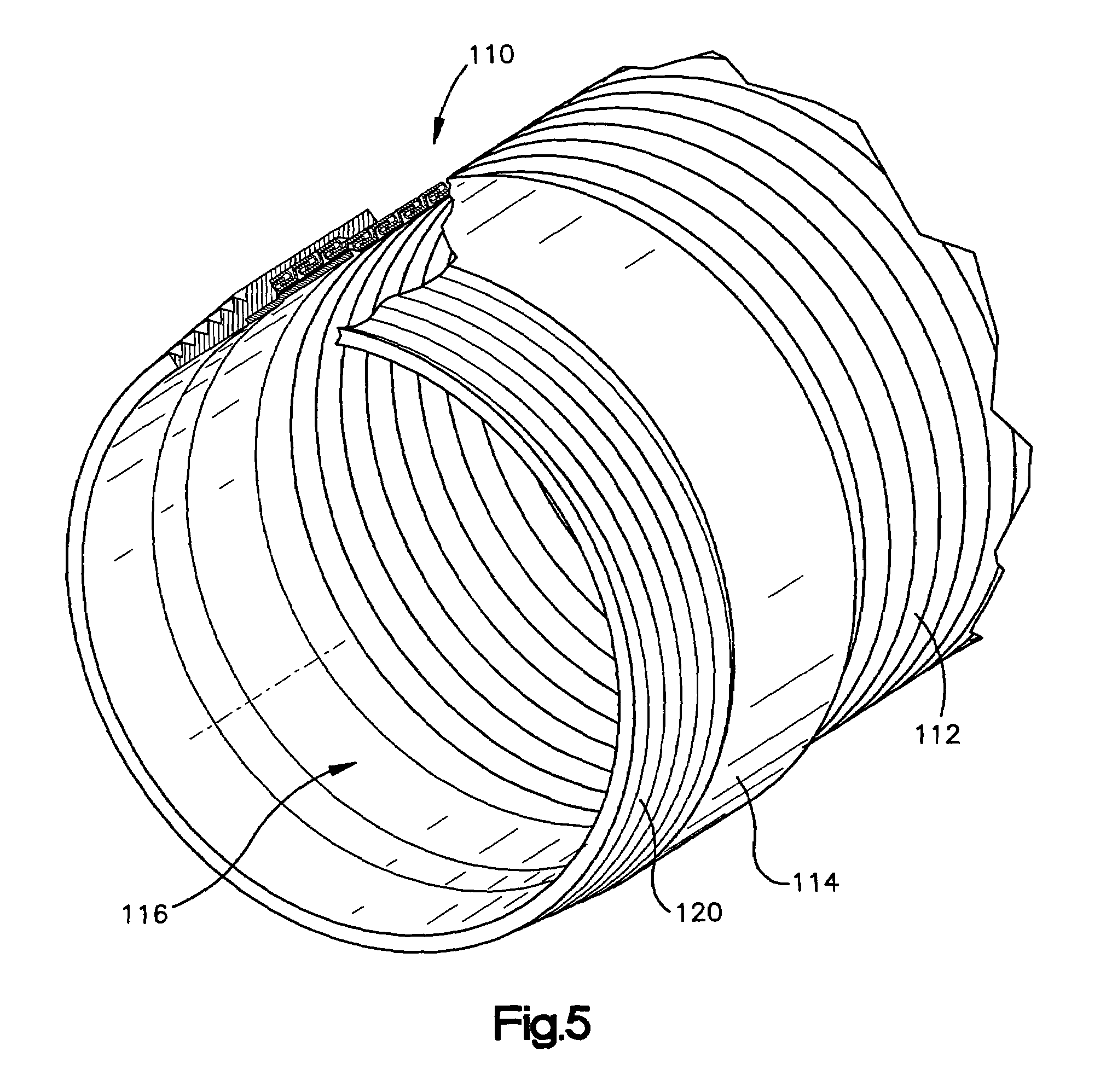
[0035]Turning now to FIGS. 5–8, a hose assembly 110 constructed in accordance with one exemplary embodiment of the invention is depicted. The hose assembly 110 includes an elongated flexible metal hose 112 attached to a hose fitting 114 having a fitting body defining a passageway 116 for conveying material. The fitting body has a mating portion 120 for connecting the hose assembly 110 to a corresponding fitting (not shown) which delivers or accepts material passing through the hose assembly 110. A sleeve 122 (see FIG. 6) frictionally engages an inner surface of the fitting body and secures an end portion 130 (see FIG. 7) of the metal conduit or hose 112 to the fitting by trapping the end portion 130 of the metal conduit or hose between the sleeve 122 and the fitting body.

[0036]In the disclosed hose assembly, an inner surface of the fitting has a stepped recess 132 (see FIG. 6) that is machined into the fitting body. A first portion of the stepped recess 132 has a cylindrical surface...


PUM

PropertyMeasurementUnit
Flexibilityaaaaaaaaaa

Abstract

A hose assembly including an elongated flexible metal hose attached to a hose fitting having a fitting body defining a passageway for conveying material. The fitting body has a mating portion for connecting the hose assembly to a corresponding fitting which delivers or accepts material passing through the hose assembly. A sleeve engages a surface of the fitting body and secures an end portion of the metal conduit to the fitting by trapping the end portion of the metal conduit between the sleeve and the fitting body. During installation, the sleeve is inserted into the body and subsequently the hose is inserted into a gap between the sleeve and fitting body. A fixture having a radially expanding member is slipped into the sleeve and brought into contact with the sleeve to deform the sleeve and consequently trap an end of the hose between the sleeve and the fitting.

Description

CROSS-REFERENCE TO RELATED APPLICATIONS[0001]This non-provisional application claims benefit of U.S. Provisional Patent Application Ser. No. 60 / 424,865, entitled “Flexible Metal Hose Assembly and Method of Making the Same,” filed on Nov. 8, 2002.FIELD OF THE INVENTION[0002]The present invention is directed to flexible metal hoses, and more specifically, the invention is directed to flexible metal hoses made from convoluted, corrugated metal ribbons.BACKGROUND ART[0003]Flexible metal hoses or conduits made from thin sheet metal ribbons which are convoluted and joined at their edges are commercially available from Hose Master Inc., assignee of the present invention. A so-called “interlocked” conduit is one example of such conduits. Interlocked conduit use thin metal ribbons wound helically with their convolutions secured together by reversely curved ribbon edges which are interlocked. The interlocked edges permit limited play between adjacent convolutions so the conduit can be flexed ...

Claims


Application Information

Patent Timeline
IPC IPC(8): F16L33/00F16L33/26
CPCF16L33/26Y10T29/53987
Inventor FOTI, SANTO
Owner HOSE MASTER
Why Eureka
Try Eureka