Supercharge Your Innovation With Domain-Expert AI Agents!

Swashplate assembly

a technology of swashplate machine and assembly, which is applied in the direction of machines/engines, positive displacement liquid engines, pump parameters, etc., can solve the problems of reducing control resolution, reducing efficiency, and relatively complex mechanical properties of swashplate machines

Active Publication Date: 2006-10-24
CONCENTRIC ROCKFORD
View PDF15 Cites 7 Cited by
  • Summary
  • Abstract
  • Description
  • Claims
  • Application Information

AI Technical Summary

Benefits of technology

This design enhances the efficiency and control precision of the hydraulic machine by minimizing mechanical and hydraulic losses, reducing friction, and maintaining high load-bearing capabilities while maintaining mechanical integrity.

Problems solved by technology

The swashplate machines are, however, relatively complex mechanically with rotating and reciprocating components that must be manufactured to withstand large hydraulic and mechanical forces.
These constraints lead to a reduction in the efficiency due to mechanical and hydraulic losses, a reduced control resolution due to the mechanical inefficiencies and the required size and mass of the components and a relatively expensive machine due to the manufacturing complexity.
However, the loads placed on such bearings may cause flexure of the swashplate between the bearings and consequent loss of precision.

Method used


Image

  • Swashplate assembly
  • Swashplate assembly
  • Swashplate assembly

Examples


Embodiment Construction

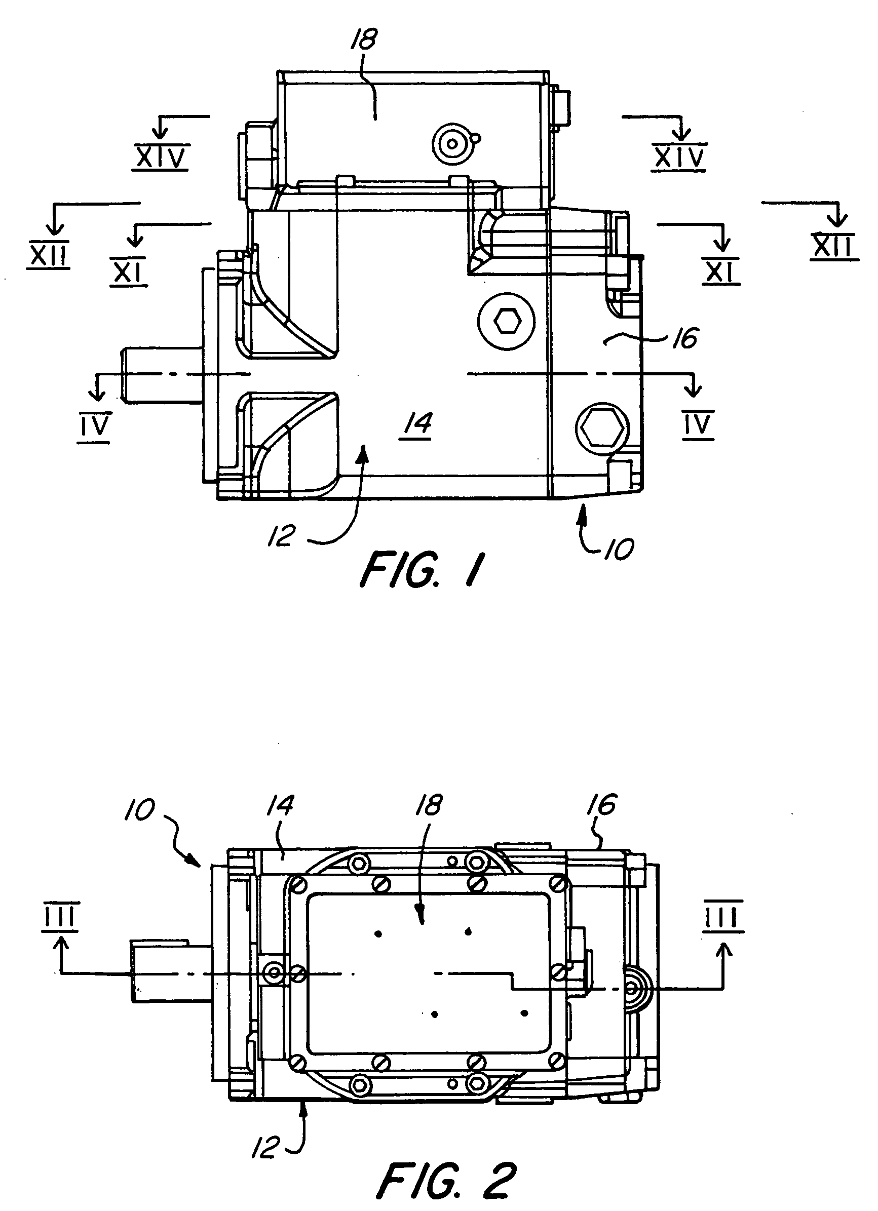
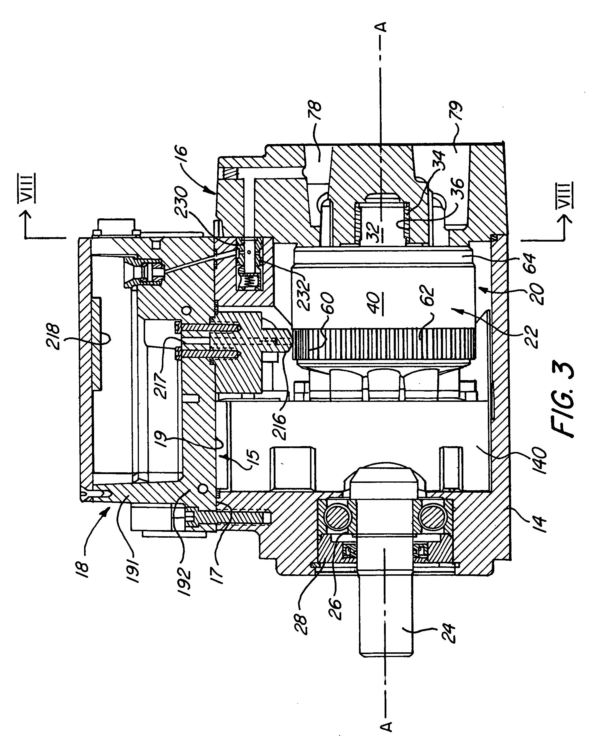
[0042]Referring therefore to FIGS. 1 through 4, a hydraulic machine 10 includes a housing 12 formed from a casing 14, an end plate 16 and a control housing 18. The casing 14 has an opening 15 on its upper side with a planar sealing surface 17 around the opening 15. The control housing 18 has a lower surface 19 that extends across the opening 15 and is secured to the casing 14. The control housing 18, end plates 16 and casing 14 define an internal cavity 20 in which the rotating group 22 of the machine 10 is located.

[0043]As can be seen in FIGS. 3, 4, 5 and 6, the rotating group 22 includes a drive shaft 24 that is rotatably supported in the casing 14 on a roller bearing assembly 26 and sealed with a seal assembly 28. One end of the drive shaft 24 projects from the casing and includes a drive coupling in the form of a key 30 for connection to a drive or driven component (not shown) e.g. an engine, electric motor or wheel assembly. The opposite end 32 of the drive shaft 24 is supporte...


PUM

PropertyMeasurementUnit
thicknessaaaaaaaaaa
pressureaaaaaaaaaa
forcesaaaaaaaaaa

Abstract

A rotary hydraulic machine has a swashplate adjustable by an actuator. The swashplate has a part cylindrical bearing surface supported by a complimentary bearing surface in the housing and a fluid bearing acts between the surfaces. The fluid is supplied to the fluid bearing by pressure compensated flow control valves to maintain a predetermined flow of fluid. The actuator includes a pair of single acting hydraulic motors secured in the housing and acting on the swashplate at spaced locations. The pistons of the hydraulic motors engage cylindrical pins located on the swashplate to permit a rolling motion between the swashplate and motors as the swashplate is adjusted.

Description

BACKGROUND OF THE INVENTION[0001]1. Field of the Invention[0002]The present invention relates to hydraulic machines.[0003]2. Description of the Prior Art[0004]There are many different types of hydraulic machines that can be used to convert mechanical energy into fluid energy and vice versa. Such machines may be used as a pump in which mechanical energy is converted into a flow of fluid or as a motor in which the energy contained in a flow of fluid is converted into mechanical energy. Some of the more sophisticated hydraulic machines are variable capacity machines, particularly those that utilize an inclined plate to convert rotation into an axial displacement of pistons or vice versa.[0005]Such machines are commonly referred to as swashplate pumps or motors and have the attribute that they can handle fluid under relatively high pressure and over significant range of flows. A particular advantage of such machines is the ability to adjust the capacity of the machine to compensate for ...

Claims


Application Information

Patent Timeline
Patent Type & Authority Patents(United States)
IPC IPC(8): F01B3/02F01B3/00F04B1/20F04B1/32
CPCF01B3/0035F01B3/007F04B1/2085F04B1/324F04B2201/0805F05C2225/00F05C2253/12
Inventor KADLICKO, GEORGE
Owner CONCENTRIC ROCKFORD
Features
  • R&D
  • Intellectual Property
  • Life Sciences
  • Materials
  • Tech Scout
  • Unparalleled Data Quality
  • Higher Quality Content
  • 60% Fewer Hallucinations
Learn More