Dual chamber lotion pump

a lotion pump and dual chamber technology, applied in the direction of liquid transfer devices, instruments, single-unit apparatuses, etc., can solve the problems of limited shelf life, liquid product effectiveness loss, and drawbacks of conventional vertically reciprocating pump dispensers

Active Publication Date: 2006-10-24
WESTROCK DISPENSING SYST
View PDF6 Cites 35 Cited by
  • Summary
  • Abstract
  • Description
  • Claims
  • Application Information

AI Technical Summary

Benefits of technology

[0011]The manually operated, vertically reciprocated pump dispenser of the invention overcomes the disadvantages associated with prior art dispensers employed in dispensing liquids comprised of at least two separate component liquids. The vertically reciprocated pump dispenser of the invention keeps the two component liquids separate from each other until they are mixed together for the first time in the discharge passage of the pump dispenser just prior to their being dispensed from the dispenser. Thus, the problems of expired shelf life and / or separation of liquid components in the container are avoided.
[0015]Pump chamber one-way valves are positioned in each pump chamber separating the interior volume of the pump chamber from the dip tubes. The pump chamber one-way valves permit the flow of liquid upwardly through the dip tubes into the pump chambers, but prevent the reverse flow of liquid from the pump chambers downwardly through the dip tubes.
[0017]Piston rod one-way valves are positioned inside the rod passages at the bottoms of the rods. The piston rod one-way valves permit the flow of liquid upwardly through the piston rod passages from the two pump chambers, but prevent the reverse flow of liquid from the two piston rod passages to the two pump chambers.
[0026]The manually vertically reciprocated pump dispenser of the invention described above provides a simplified construction of a pump dispenser that can draw two separate liquids from a liquid container and keep the two separate liquids separated from each other as they are pumped through the dispenser until they are mixed for the first time just prior to their being dispensed from the dispenser.

Problems solved by technology

However, the conventional vertically reciprocating pump dispenser has drawbacks when employed with certain types of liquids.
Certain liquids dispensed from conventional vertically reciprocated pump dispensers are the product of two or more separate liquid components that remain stable while separated but have a limited shelf life when they are mixed together.
Reciprocating pump dispensers that are attached to containers containing liquids of this type cannot remain in storage or on a store shelf for a prolonged period of time before the liquid product begins to lose its effectiveness.

Method used


Image

  • Dual chamber lotion pump
  • Dual chamber lotion pump
  • Dual chamber lotion pump

Examples


Embodiment Construction

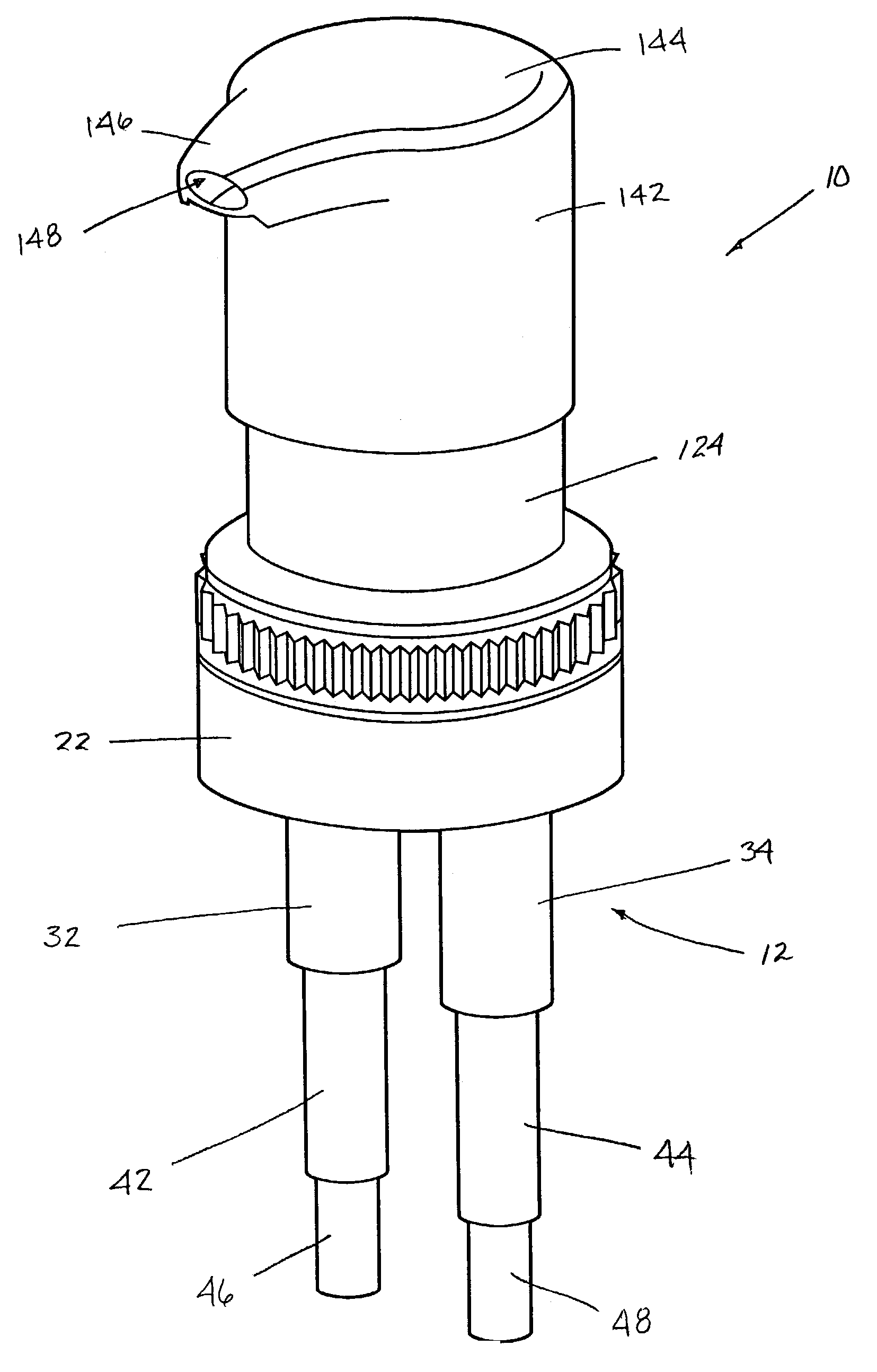
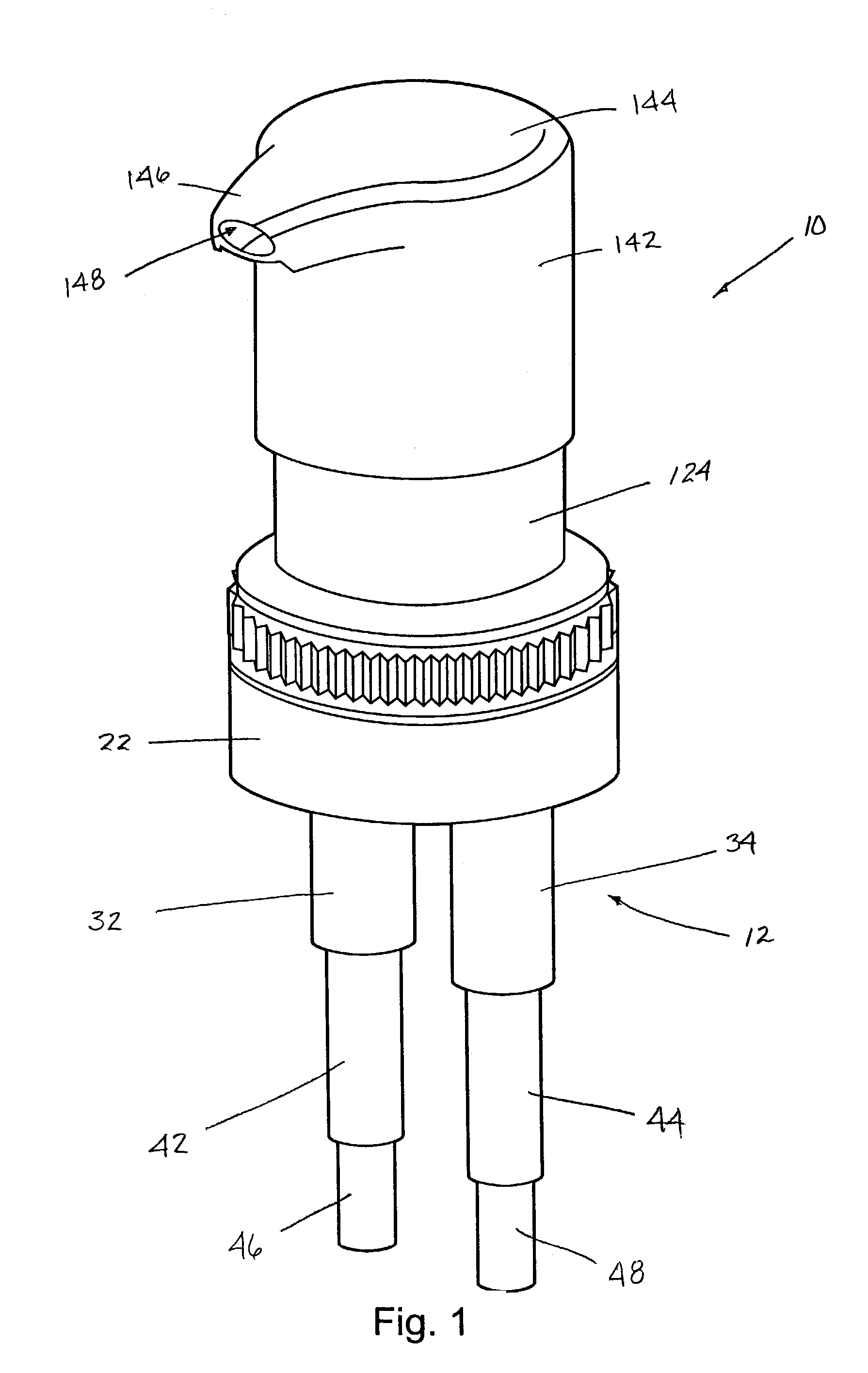
[0031]As stated earlier, the manually operated, vertically reciprocated pump dispenser of the invention is designed to be attached to a container containing two separate liquid components. The pump dispenser of the invention may be connected to two separate containers containing the two separate liquid components. Alternatively, the pump dispenser of the invention may be connected to a single liquid container having a partition in the interior of the container that divides the interior into two separate container volumes containing the separate liquid components.

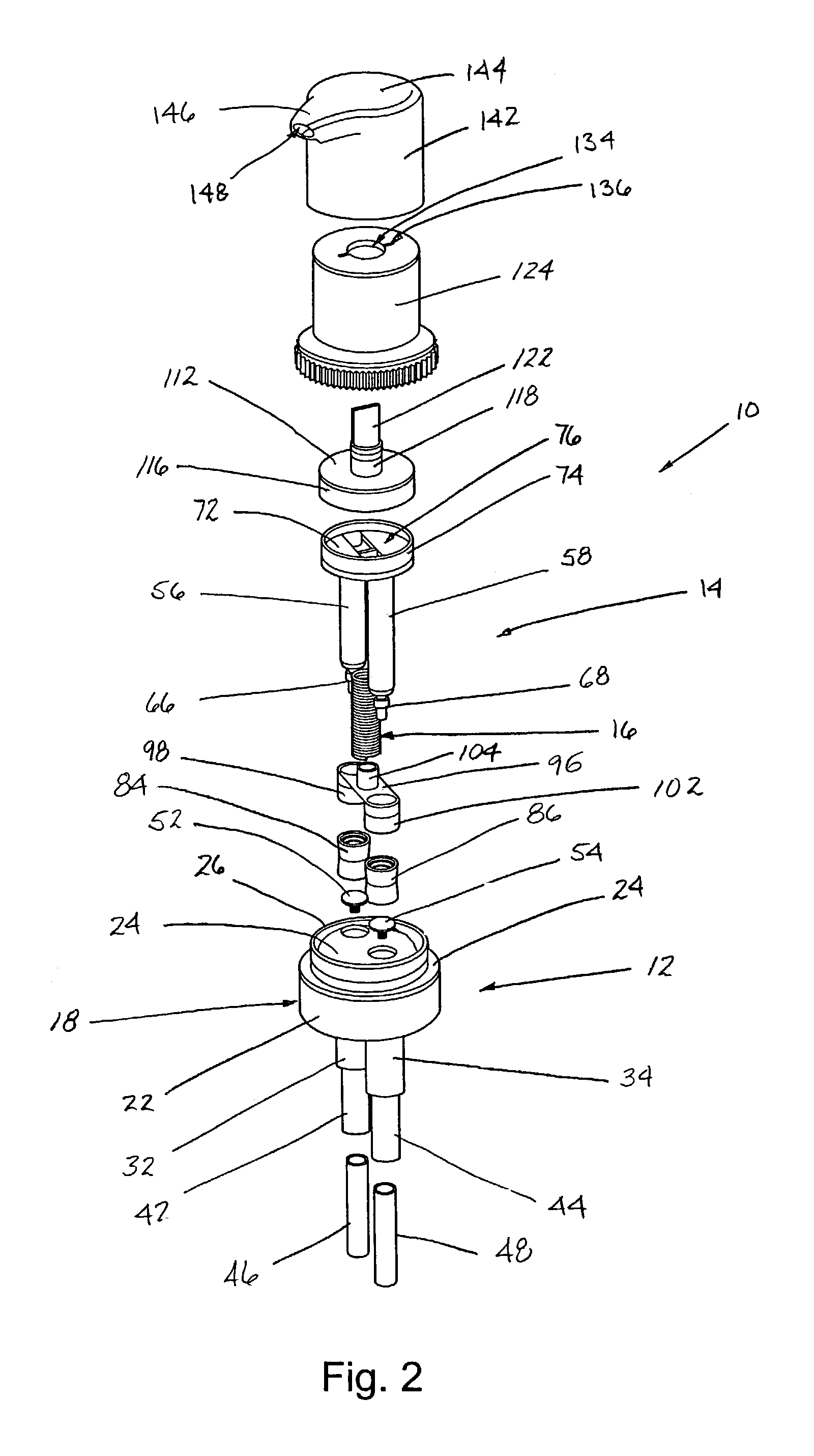
[0032]The dispenser 10 of the invention is basically comprised of a pump housing 12 and a plunger housing 14 that is mounted in the pump housing for manual, vertical reciprocating movement of the plunger housing 14 in the pump housing 12. In the preferred embodiment of the dispenser, the component parts of the dispenser are constructed of resilient plastic materials except for a metal coil spring 16 that biases the pump plun...


PUM


Abstract

A manually operated vertically reciprocated pump dispenser has a simplified construction with two separate pumps that pump two separate liquids from a container and keep the two separate liquids separated from each other as they are pumped through the dispenser, mixing the liquids for the first time in a discharge passage of the dispenser just prior to the mixed liquids being discharged from the dispenser.

Description

BACKGROUND OF THE INVENTION[0001](1) Field of the Invention[0002]The present invention pertains to a manually operated dispenser that is connectable to two container volumes containing separate liquids. The dispenser has two separate pump assemblies that draw the separate liquids from the container volumes and then mix the liquids before they are dispensed by the dispenser. The two separate pump assemblies are vertically oriented and are manually vertically reciprocated pump assemblies.[0003](2) Description of Related Art[0004]Manually operated vertically reciprocated pumps, often referred to as lotion pumps or hand lotion pumps, typically include a pump housing that is attached to the neck of a container containing liquid and a manually operated pump plunger that extends vertically downwardly into the pump housing.[0005]The pump housing includes a pump chamber that is located in the interior of the container of liquid. A dip tube extends downwardly from the pump chamber into the li...

Claims


Application Information

Patent Timeline
Patent Type & Authority Patents(United States)
IPC IPC(8): B67D5/52B67D7/70B05B11/00B67D7/58B67D7/78B67D99/00
CPCB05B11/3084B05B11/1084
Inventor FOSTER, DONALD D.NELSON, PHILIP L.
Owner WESTROCK DISPENSING SYST
Why Eureka
Try Eureka