Drive device

Active Publication Date: 2006-10-24
FUJIFILM HLDG CORP +1
View PDF2 Cites 10 Cited by
  • Summary
  • Abstract
  • Description
  • Claims
  • Application Information

AI Technical Summary

Benefits of technology

[0014]In view of the aforementioned, an object of the present invention is to provide a drive device capable of precisely adjusting a projecting height of a releasing portion (i.e., a releasing operating membe

Problems solved by technology

In this way, even there exists a size error between the drive device and the recording tape cartridge (brake member) due to f

Method used


Image

  • Drive device
  • Drive device
  • Drive device

Examples


Embodiment Construction

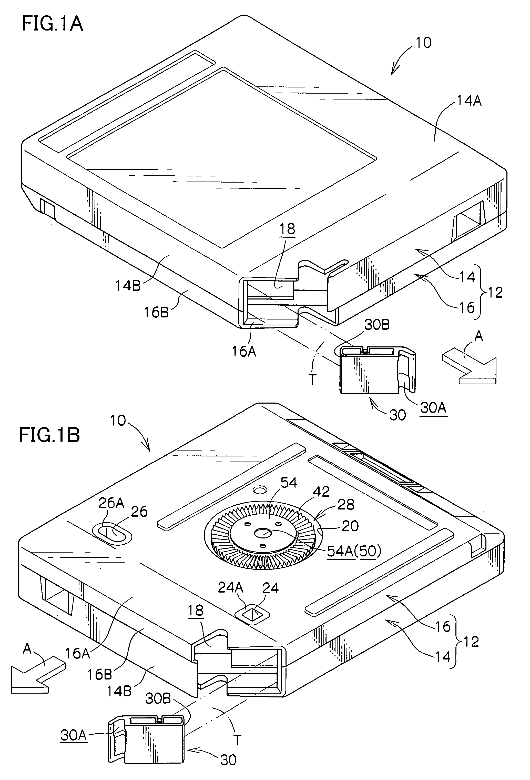
[0037]A drive device according to an embodiment of the present invention will be described on the basis of the drawings. First, a recording tape cartridge (magnetic tape cartridge) 10 which can be loaded into the drive device will be described. Note that, for convenience of explanation, the direction of loading the recording tape cartridge 10 into the drive device of is denoted by arrow A, and this direction of arrow A is the forward direction (front side) of the recording tape cartridge 10.

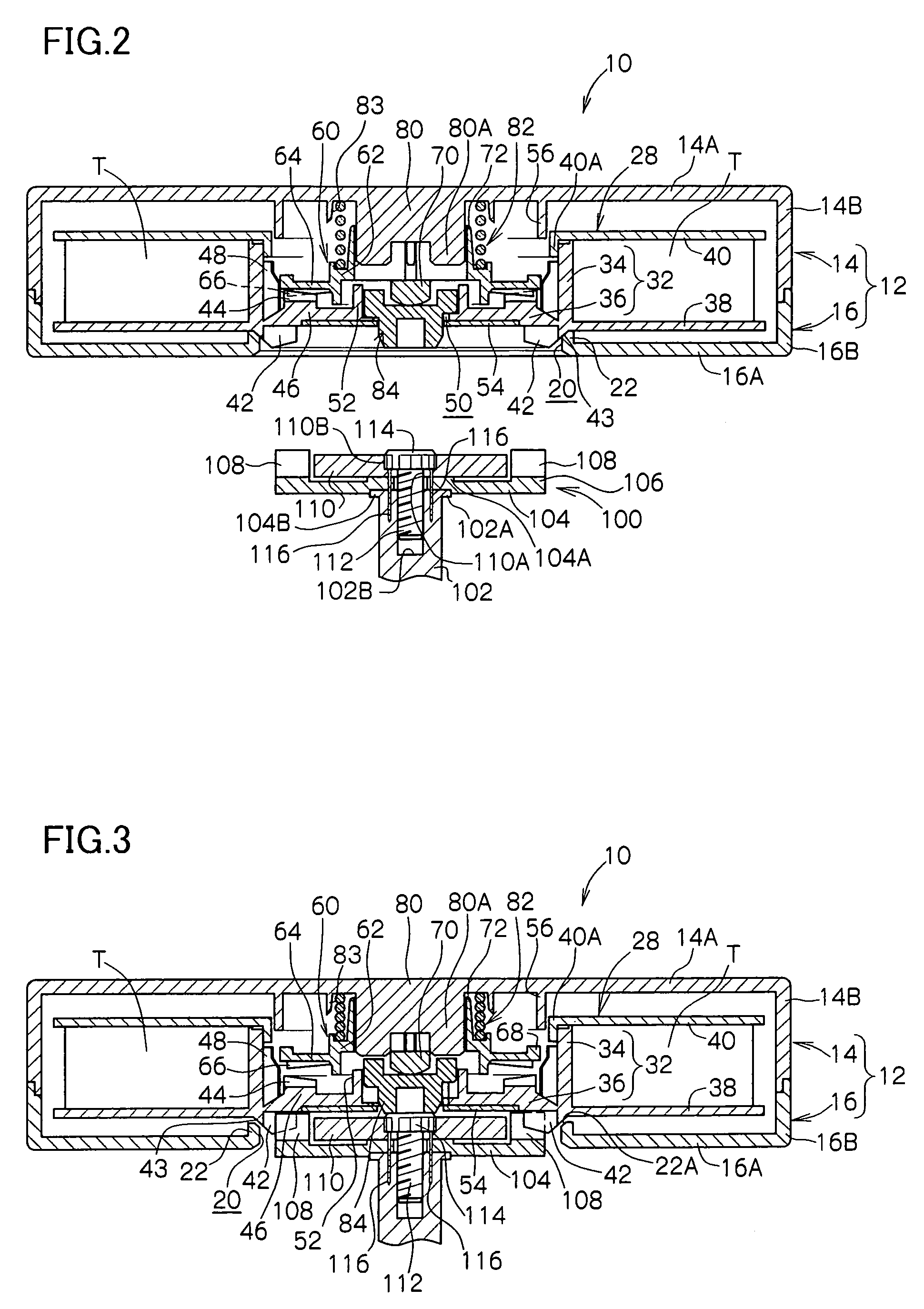
[0038]As shown in FIGS. 1A through 3, the recording tape cartridge 10 has a case 12. The case 12 is structured by an upper case 14 and a lower case 16 being joined together. Specifically, the upper case 14 is structured such that a substantially frame-shaped peripheral wall 14B stands erect along the outer edge of a ceiling plate 14A which is substantially rectangular in plan view. The lower case 16 is structured such that a peripheral wall 16B stands erect along the outer edge of a floor plate 1...


PUM


Abstract

A drive device to which a recording tape cartridge is loaded, and which can record information in a recording tape and playback information recorded in the recording tape, the drive device includes: a rotating shaft having a drive gear which meshes with the reel gear of the cartridge and rotates the reel of the cartridge; an operating member which pushes up the brake member of the cartridge to the reel rotation permitted position; and an adjusting mechanism which adjusts a projecting height of the operating member.

Description

CROSS-REFERENCE TO RELATED APPLICATION[0001]This application claims priority under 35 USC 119 from Japanese Patent Application No. 2003-150341, the disclosure of which is incorporated by reference herein.BACKGROUND OF THE INVENTION[0002]1. Field of the Invention[0003]The present invention relates to a drive device which can record and playback information into and from a recording tape, and a recording tape cartridge is mounted in the drive device. The recording tape cartridge accommodating, within a case, a single reel on which is wound a recording tape, such as a magnetic tape, which is used as a recording / playback medium mainly for computers or the like.[0004]2. Description of the Related Art[0005]Conventionally, recording tape cartridges (e.g., magnetic tape cartridge) have been known in which a magnetic tape, which is used as a data recording / playback medium for a computer or the like, is wound on a single reel, and the reel is accommodated in a synthetic resin case. The record...

Claims


Application Information

Patent Timeline
IPC IPC(8): G11B23/04G11B15/30
CPCG11B23/044
Inventor HIRAGUCHI, KAZUO
Owner FUJIFILM HLDG CORP
Why Eureka
Try Eureka