Automatic clamp apparatus for IV infusion sets used in pump devices

a technology of clamping apparatus and pump device, which is applied in the direction of mechanical apparatus, engine diaphragm, diaphragm valve, etc., can solve the problems of uncontrollable infusion of medication into the patient, unfavorable “free flow” of medical fluids, and require some manipulation skill on the part of the attending technician, so as to facilitate the operation of the clamping apparatus in the infusion pump

Active Publication Date: 2006-10-24
CAREFUSION 303 INC
View PDF10 Cites 80 Cited by
  • Summary
  • Abstract
  • Description
  • Claims
  • Application Information

AI Technical Summary

Benefits of technology

[0012]In further aspects in accordance with the invention, the slide clamp further comprises a front pushing flange large enough to receive a digit of an operator used to push the clamp apparatus into position in a medical infusion pump, the pushing surface being concave. The release tab of the locking arm is located at a position other than behind the pushing flange. In a much more detailed aspect, the release tab is located at a sideways position in relation to the pushing flange. Additionally, the base comprises a rounded mounting end whereby pressing the clamp into operative position in an infusion pump is facilitated.

Problems solved by technology

“Free flow” of medical fluids is undesirable since the flow of the fluid is uncontrolled and the prescribed treatment is not followed.
This could result in the uncontrolled infusion of medication into the patient under the influence of the static head pressure in the tube, or blood from the patient could flow back into the IV tube.
The manual devices require some manipulation skill on the part of the attending technician, and there is always the chance that the technician will forget to properly time the manual clamping process of the tube before the door of the pump is opened.
Furthermore, the door may be accidentally opened, resulting in free flow in the tube.
However, there still can occur the possibility of an inadvertent free flow of fluid through the IV tube due to operator error in regard to use of such devices.

Method used


Image

  • Automatic clamp apparatus for IV infusion sets used in pump devices
  • Automatic clamp apparatus for IV infusion sets used in pump devices
  • Automatic clamp apparatus for IV infusion sets used in pump devices

Examples


Embodiment Construction

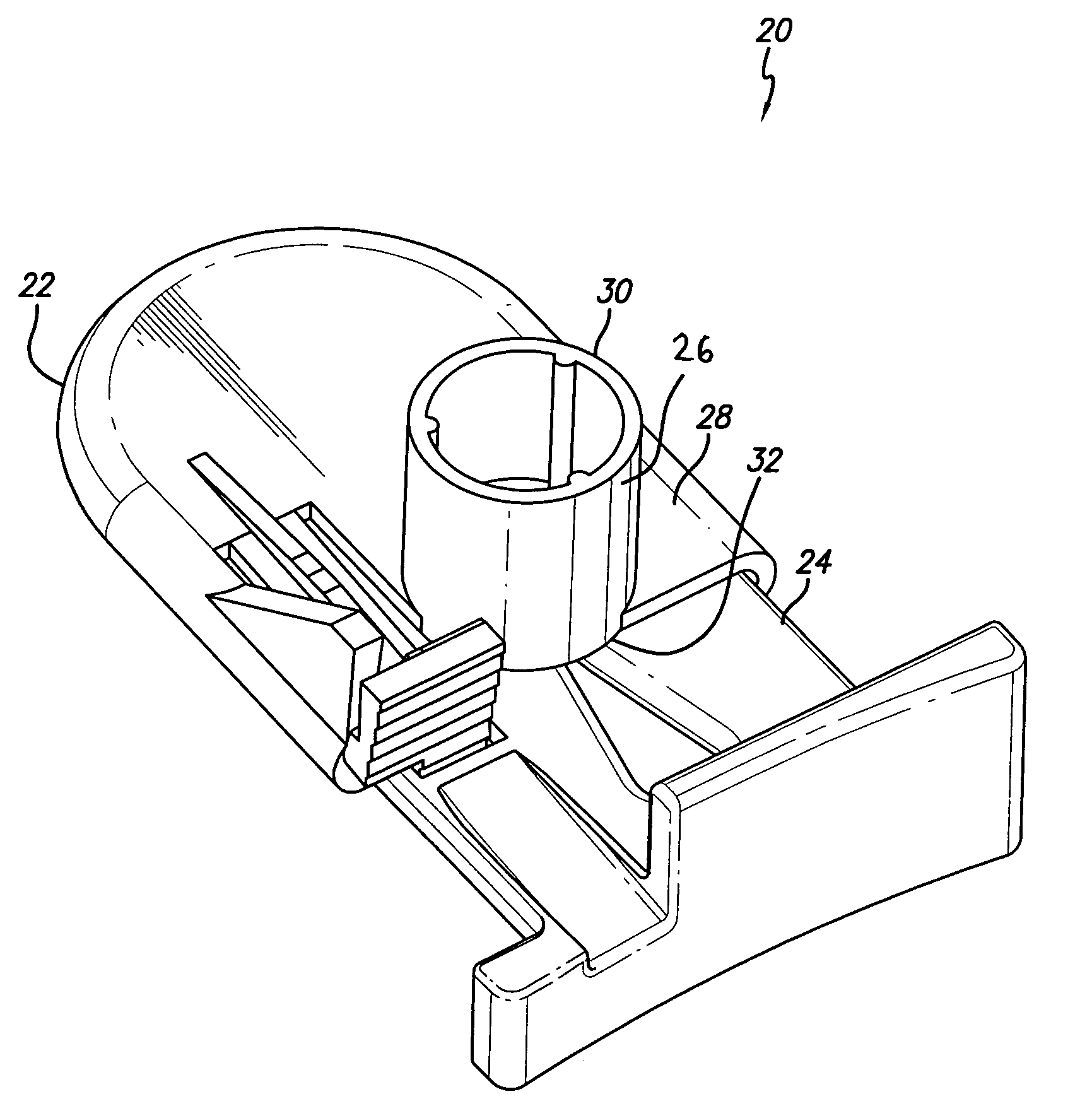
[0029]Referring now to the drawings with more particularity, in which like reference numerals refer to like or corresponding elements among the several views, FIG. 1 presents an automatic clamp apparatus 20 for intravenous (herein referred to as “IV”) infusion sets used in pump devices. The clamp apparatus 20 comprises generally a relatively open, box shaped base or frame 22 and a mating slide clamp 24. Both parts can be formed by injection molding from various plastic materials. The solid body of the slide clamp 24 is shaped and sized to slide within the base 22. In the embodiment shown, the base 22 has a tower 26 formed on the top surface 28 of the base, with the tower extending upwardly from the base and substantially perpendicular to the base. The top end 30 of the tower 26 is formed as a female tube connector into which a resilient IV tube can be attached. A pumping tube or other type of fluid conduit can be attached to the base by other means if desired. The open bottom end 32...


PUM


Abstract

A clamp apparatus for selectively occluding a resilient tube to prevent free flow of fluid in the tube. The device comprises a base member to which the resilient IV tube is attached or through which it passes, and a slide clamp that slides relative to the base member and relative to the tube. The aperture in the slide clamp has a relatively open hole at one end, through which the tube passes when the slide clamp is an open position, allowing fluid to flow through the tube. The aperture also has a relatively constricted slot at the other end, through which the tube passes when the slide clamp is in the occluding position, preventing fluid flow through the tube. A deflectable cantilevered locking arm on the base interlocks with a detent on the slide clamp to lock the slide clamp at the occluding position to avoid inadvertent free flow. A release tab that is used to release the locking arm from the slide clamp is located off center to avoid inadvertent activation. The deflectable arm is unstressed when the slide clamp is in either the occluding or the open positions. A stop device prevents over-stressing the release tab when it is moved. In one embodiment, the clamp apparatus may be slid along the IV tube to a desired location.

Description

FIELD OF INVENTION[0001]The invention is generally related to clamps used on flexible IV tubing in the field of intravenous (IV) infusion devices such as peristaltic pumps, and more particularly, to clamping devices used to prevent the free flow of fluids through an IV tube when the infusion pump is disengaged from the IV tube.BACKGROUND OF THE INVENTION[0002]It is a common practice to deliver fluids such as medications to a patient intravenously by means of a pumping device, such as a peristaltic pump. Such pumps are useful because they can deliver the medication in a highly controlled and precise fashion, and because they do so without coming in contact with the medication. The fluid is moved through a flexible IV tube by pressing a pumping member against the tube sufficiently to move the fluid in the tube downstream towards the patient. In the case of peristaltic mechanisms having multiple pumping fingers, the fingers are moved against the tube in a sequential manner from upstrea...

Claims


Application Information

Patent Timeline
Patent Type & Authority Patents(United States)
IPC IPC(8): F16K7/04A61M39/28F16K7/06
CPCA61M39/287F16K7/066A61M39/281
Inventor CLARKE, CHRISTOPHER J.RUEDI, RENE
Owner CAREFUSION 303 INC
Why Eureka
Try Eureka