Centrifugal pump improvements

a centrifugal pump and centrifugal technology, applied in the field of centrifugal pumps, can solve the problems of chopper pumps subject to more wear, pumps designed for slicing or chopping solid materials may have a loss of efficiency or lower head, and material is not completely cut effectively, so as to improve the suction lift, improve the chopping effect and the pump efficiency.

Inactive Publication Date: 2006-10-24
VAUGHAN
View PDF4 Cites 41 Cited by
  • Summary
  • Abstract
  • Description
  • Claims
  • Application Information

AI Technical Summary

Benefits of technology

[0005]The present invention provides improvements for centrifugal pumps and particularly centrifugal chopper pumps for pumping liquids and slurries containing solid matter. In one aspect of the present invention, a modified seal design helps to prevent material from advancing toward relatively rotatable seal components. In another aspect of the invention, modifications are made in the pump intake plate to increase chopping effectiveness and pump efficiency. In another aspect of the invention, an impeller having vanes with a unique shape are provided to achieve improved suction lift. In another aspect of the invention, a self-priming pump is provided. A further aspect of the present invention is the provision of a centrifugal pump having an improved mechanism for adjusting the clearance between the outer edges of the impeller vanes and the interior of an adjacent intake plate.

Problems solved by technology

Depending on the material being pumped, there still may be problems with solid material working its way between cooperating parts of a pump seal, or becoming wrapped around rotating components of the pump, including the pump drive shaft.
Some materials are not completely cut effectively in the known designs, and pumps designed for slicing or chopping solid materials may have a loss of efficiency or lower head as compared to units designed for pumping only liquid.
Further, chopper pumps are subject to more wear in the area of the exposed edges of the impeller vanes and, therefore, require adjustment of the distance from the vane edges to an adjacent intake plate.

Method used


Image

  • Centrifugal pump improvements
  • Centrifugal pump improvements
  • Centrifugal pump improvements

Examples


Embodiment Construction

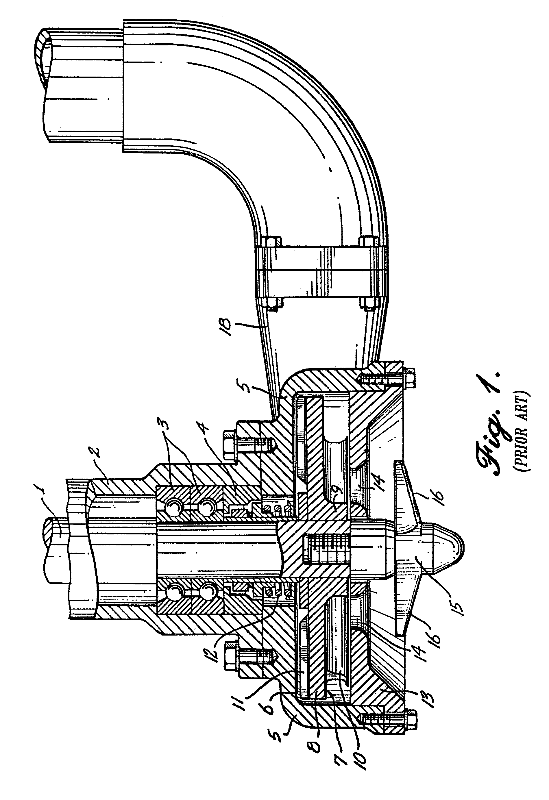
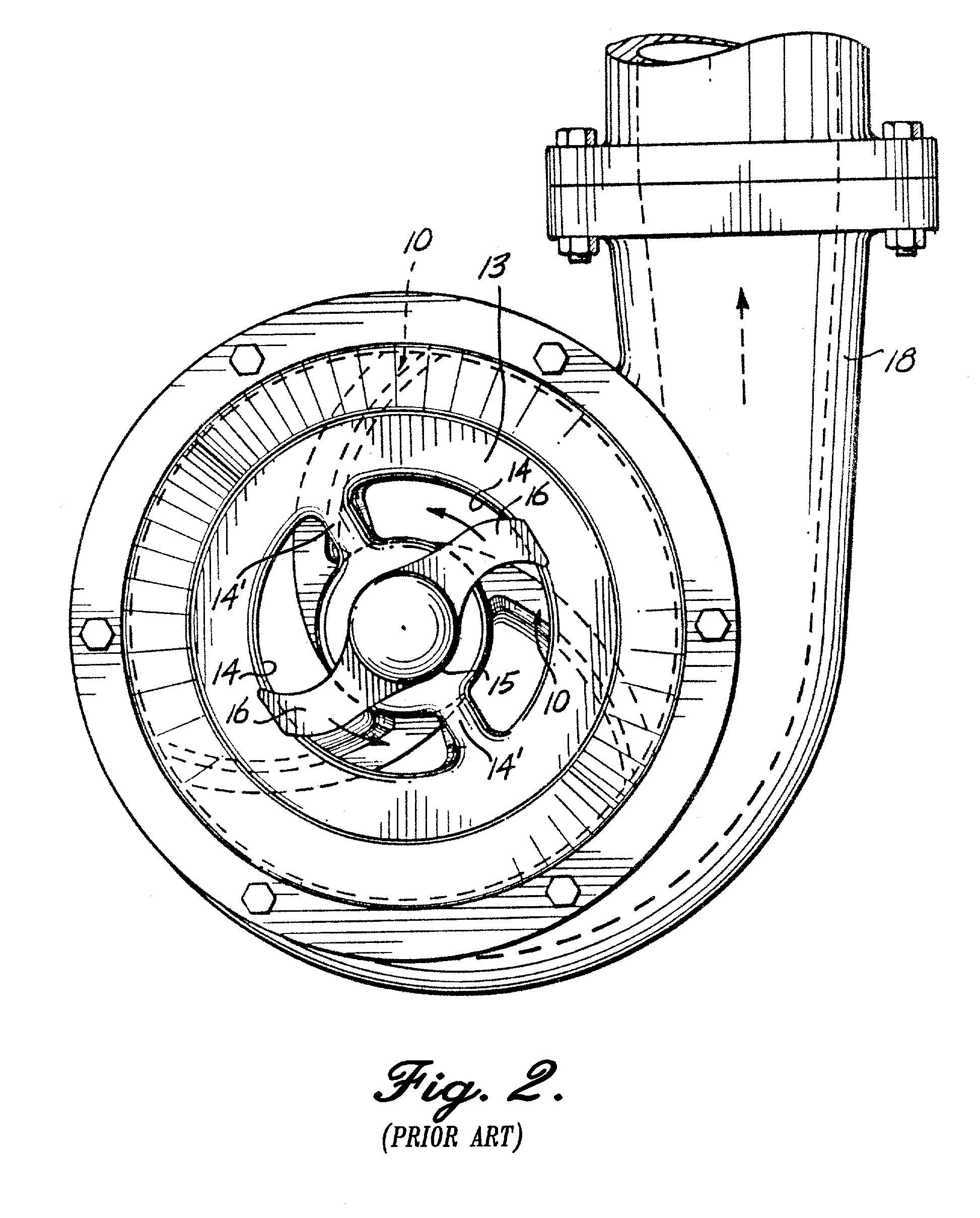
[0025]FIG. 1 and FIG. 2 show a centrifugal pump of the general type with which the improvements of the present invention may be used. As indicated in FIG. 1, the pump includes an upright drive shaft 1 received within a column 2 forming a reservoir for oil or other lubricant. The bottom of the reservoir is closed by conventional anti-friction bearings 3 and a seal 4 which includes a spring 12. The bottom portion of the column 2 is bolted to a pump casing 5 having a downward opening cavity or bowl 6 receiving the pump impeller 7. Such impeller consists of: a cylindrical shroud disk or plate 8 projecting radially from the impeller hub 9 fixed to the drive shaft; the primary pumping vanes or blades 10 projecting downward from the shroud plate; and vanes or ribs 11 projecting upward from the upper face of the shroud plate opposite the primary pumping blades 10.

[0026]The bottom of the pump bowl is closed by an endplate 13 clamped or bolted to the bottom of the pump casing and having inlet...


PUM


Abstract

An improved mechanism is provided for adjusting the clearance between the outer edges of impeller vanes of a centrifugal pump and the interior surface of an adjacent intake plate. The impeller having the vanes is mounted as an assembly to a back plate that can be secured to a casing or housing to which the intake plate is mounted. Threaded adjusters allow adjustment of the clearance between the impeller vanes and the intake plate. Additional modifications include a modified seal design to prevent material from clogging relatively rotatable seal components, a modified intake plate with a shallow recess to increase chopping effectiveness and pump efficiency, impeller vanes with a unique shape to achieve a high head, and a self-priming pump.

Description

CROSS-REFERENCE TO RELATED APPLICATIONS[0001]This application is a continuation of international application No. PCT / US00 / 27778, filed on Oct. 6, 2000, published in English on Apr. 12, 2001, designating the United States, and claiming the benefit of U.S. provisional application No. 60 / 158,014, filed on Oct. 6, 1999.FIELD OF THE INVENTION[0002]The present invention relates to a centrifugal pump, and particularly to a centrifugal pump effective for pumping liquids and slurries containing solid matter.BACKGROUND OF THE INVENTION[0003]U.S. Pat. No. 5,460,482 discloses a centrifugal chopper pump designed for pumping liquids and slurries containing solid matter, including various types of refuse, and for chopping the solid matter which may thereafter be processed for disposal. The pump has external and internal cutters rotated with the internal pump impeller. The impeller has blades or vanes that sweep across arcuate intake apertures for a slicing action of solid matter in the liquid or s...

Claims


Application Information

Patent Timeline
Patent Type & Authority Patents(United States)
IPC IPC(8): F04D29/70F04D7/04F04D29/12F04D29/16F04D29/62
CPCF04D7/045F04D29/126F04D29/165F04D29/628F04D29/622
Inventor DORSCH, GLENNKEERAN, KENT H.SWENSON, ARNE E.
Owner VAUGHAN
Why Eureka
Try Eureka