
Toroidal type continuously variable transmission

a technology of continuously variable transmission and traction type, which is applied in the direction of friction gearings, gear lubrication/cooling, gear lubrication, etc., can solve the problems of inability to meet the requirements of down sizing and weight saving, the construction of the continuously variable transmission is simplified and compact, and the manufacturing and assembling work of the continuously variable transmission is easy. , the effect of improving the reliability

Inactive Publication Date: 2006-10-24
TOYOTA JIDOSHA KK
View PDF22 Cites 1 Cited by
  • Summary
  • Abstract
  • Description
  • Claims
  • Application Information

AI Technical Summary

Benefits of technology

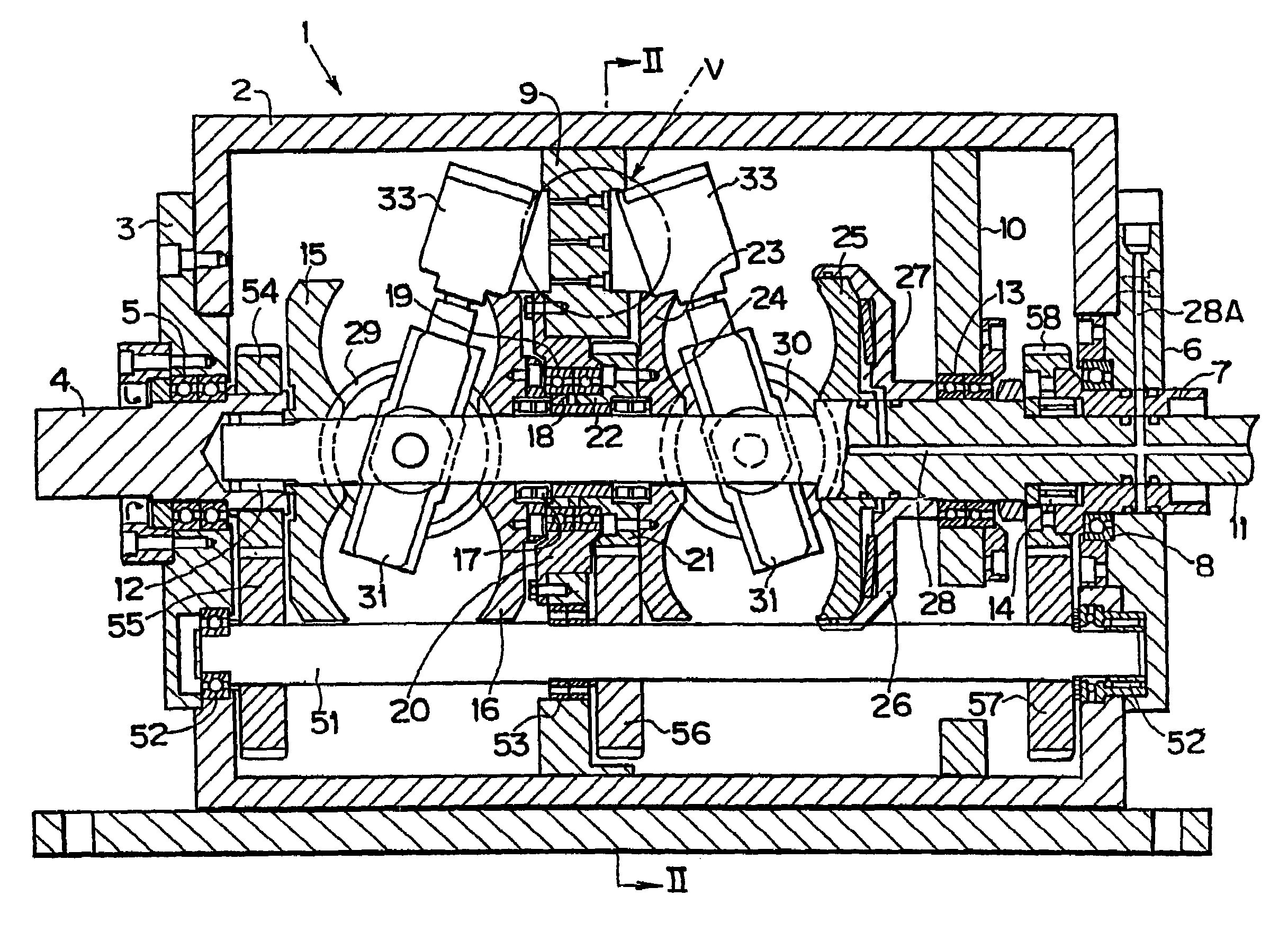
[0012]Accordingly, in the present invention, the roller is rotated by means of rotating the input disc, then, the output disc turns in connection, and the torque is transmitted between the input disc and the output disc as a result. Also, if the roller is moved by the actuator backward and forward when the torque is being transmitted, the roller is inclined to lean its rotating face against the center axis of rotation of each discs. Consequently, radial position of the contact portion between the roller and the input disc and radial position of the contact portion between the roller and the output disc are varied, and speed change is thereby executed. The actuator is fixed on the installation portion arranged inside of the housing with protruding to the center portion; therefore, portions protruding outwardly are eliminated or reduced on the housing, and entire profile of the continuously variable transmission is simplified.
[0014]With this construction, accordingly, when a hydraulic pressure is fed to the oil passage formed on the installation portion or the wall portion, the hydraulic pressure is fed to the actuator side through the port formed on the wall portion and through the port of the actuator formed on the position which corresponds to said port. Therefore, it is unnecessary to arrange pipelines for feeding and draining hydraulic pressure, and entire construction of the continuously variable transmission may be simplified and compacted. Furthermore, the oil passage may be arranged inside of the housing and the wall portion as those are manufactured, so that the manufacturing and assembling works of the continuously variable transmission become easy.

Problems solved by technology

However, if it is constructed as such and employed as a speed change device for a vehicle, mountability becomes worse because the structure has to be complicated due to big convexes and concaves, and the requirement for down sizing and weight saving cannot be fulfilled accordingly.
Moreover, productivity also becomes worse because a plurality of core and sand cast have to be employed for casting a housing.
However, in the aforementioned structure in which a plurality of actuators is held with being protruded from the housing in the radius direction, the structure of piping to the actuators becomes complicated.
Consequently, there are disadvantages such as lag in the action timing between individual actuator and so on.

Method used


Image

  • Toroidal type continuously variable transmission
  • Toroidal type continuously variable transmission
  • Toroidal type continuously variable transmission

Examples


Embodiment Construction

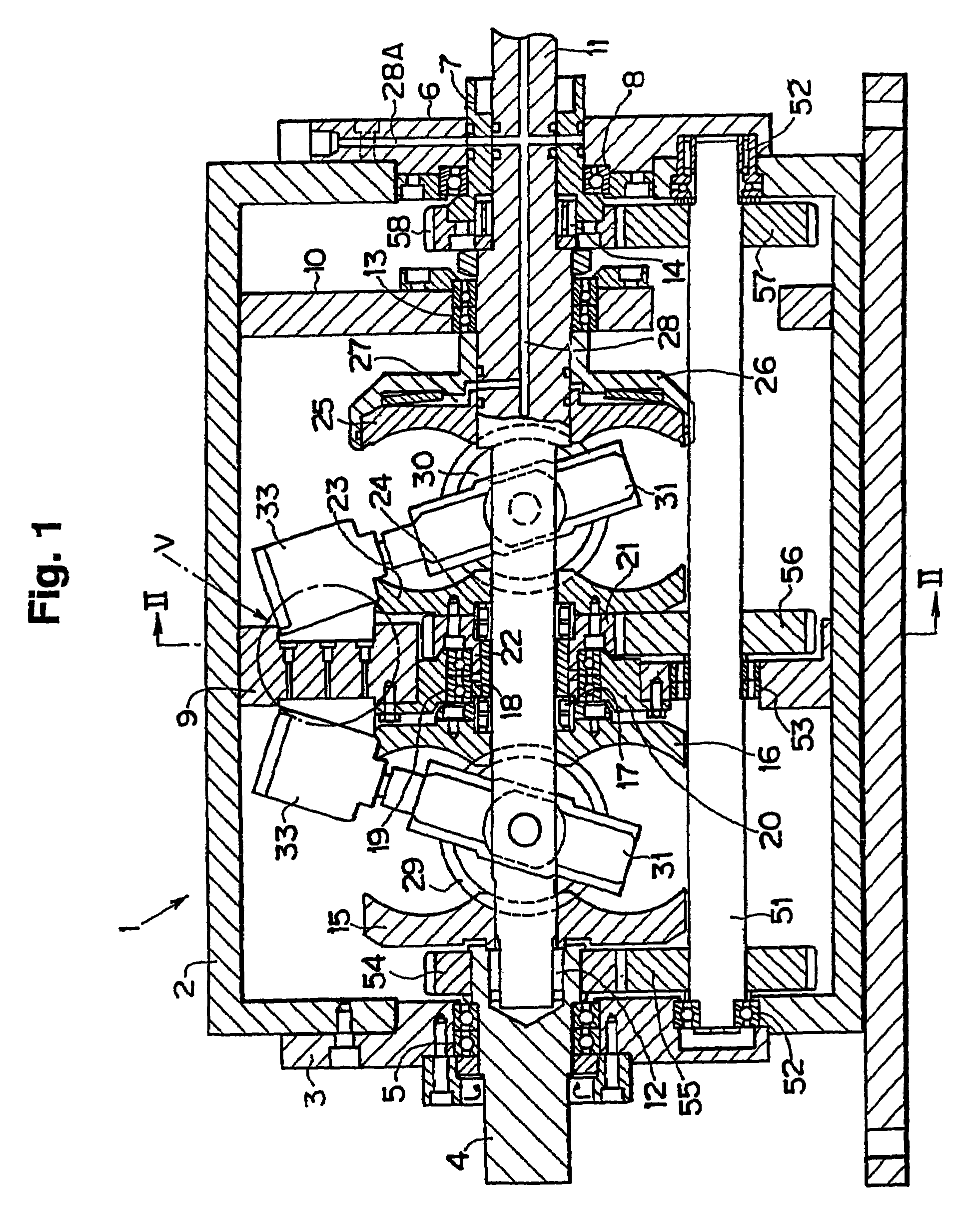
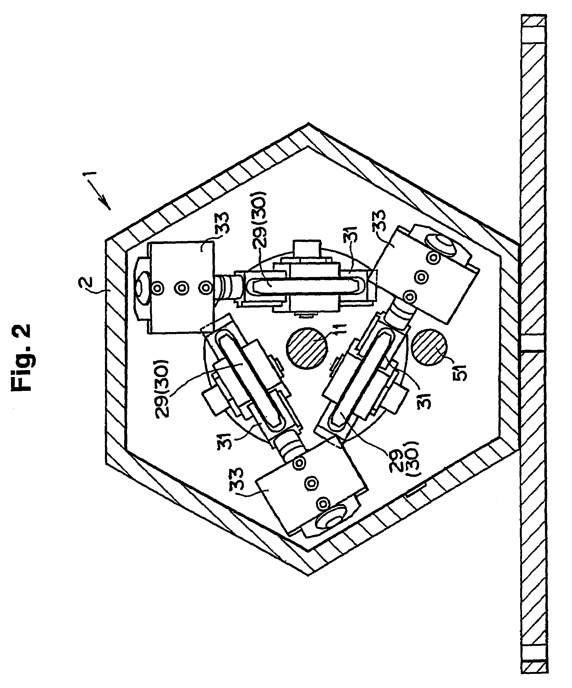
[0020]Next, this invention will be described in connection with a specific embodiment with reference to the drawings. FIG. 1 is a sectional view shows one example of the present invention, and a double cavity type full-toroydal continuously variable transmission 1 is depicted therein. The continuously variable transmission 1 as a whole is accommodated in the housing 2. The housing 2 is structured cylindrically and hollowly, and its sectional configuration is hexagonal in this example, as shown in FIG. 2.

[0021]An input shaft 4 is arranged with penetrating the center portion of an end plate 3 as one of the end plates of the housing 2, and is held by the end plate 3 through a bearing 5. Also, a cylindrical shaft 7 is arranged with penetrating the center portion of another end plate 6, and is held by the end plate 6 through a bearing 8. Moreover, an intermediate plate 9 protruding from the inner face to the center portion, i.e., the intermediate plate 9 functions as a wall portion for d...


PUM


Abstract

A toroydal type continuously variable transmission wherein a rollers is clamped in a rotatable condition by the input disc and the output disc arranged rotatably on the common axis line and opposed to each other; wherein an actuator for moving the roller backward and forward in the direction along a plane vertical to a center axis of rotation of those discs is provided; and wherein those discs, roller, and actuator are accommodated inside of the housing; and an installation portion protruding to the center portion of the housing is provided on inner face of the housing and the said actuators are fixed on the installation portion.

Description

TECHNICAL FIELD[0001]This invention relates to a toroidal type (or traction type) continuously variable transmission which is constructed with clamping rollers for mediating the transmission of a torque between a rolling face of an input disc and a rolling face of an output disc opposed to each other, in order to transmit a torque between the individual discs through the rollers.BACKGROUND ART[0002]A continuously variable transmission of this kind is constructed with, e.g., clamping a disc-shaped rollers between a pair of discs arranged opposed to each other. The portion of the pair of discs where is the outer side from a predetermined radius has an arcuate plane congruent with the arc centered on the center points of opposed planes of those discs, and such arcuate planes is leading to circumferential direction. The plane thus incurved three-dimensionally is a toroidal plane. The toroidal plane functions as a rolling face and the rollers is clamped therebetween. The roller is a disc...

Claims


Application Information

Patent Timeline
IPC IPC(8): F16H15/38F16H57/023F16H57/04
CPCF16H15/38
Inventor TAKETSUNA, YASUJITAMAKI, SHIGENORI
Owner TOYOTA JIDOSHA KK
Learn More