Difference amplifier for regulating voltage

a voltage regulation and amplifier technology, applied in the field of electronic circuits, can solve the problems of circuit error in output voltage as the output current varies, volts are approximately 20 to 30 millivolts, etc., and achieve the effect of avoiding the effect of output dependent current loading effects through the impedan

Active Publication Date: 2006-10-24
NAT SEMICON CORP
View PDF17 Cites 23 Cited by
  • Summary
  • Abstract
  • Description
  • Claims
  • Application Information

AI Technical Summary

Benefits of technology

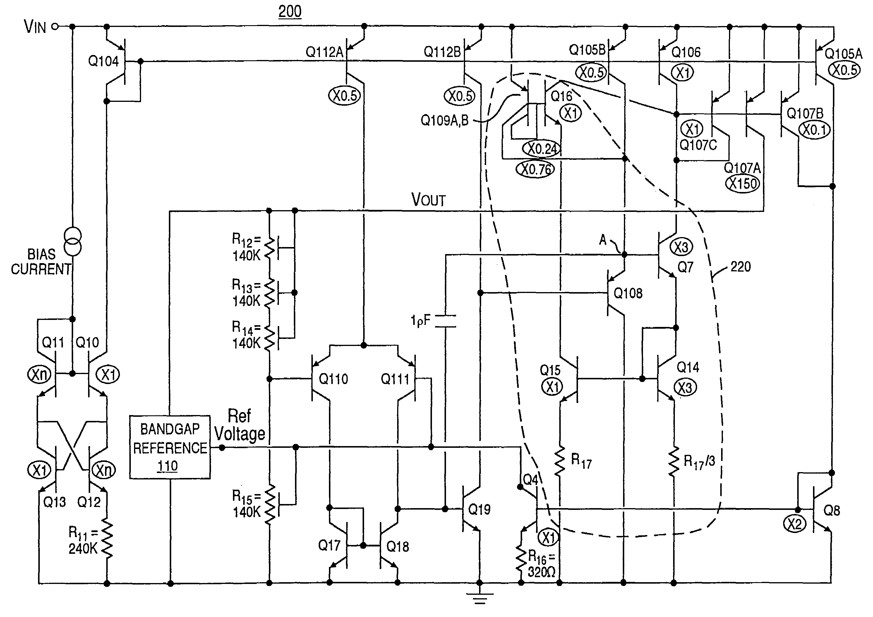
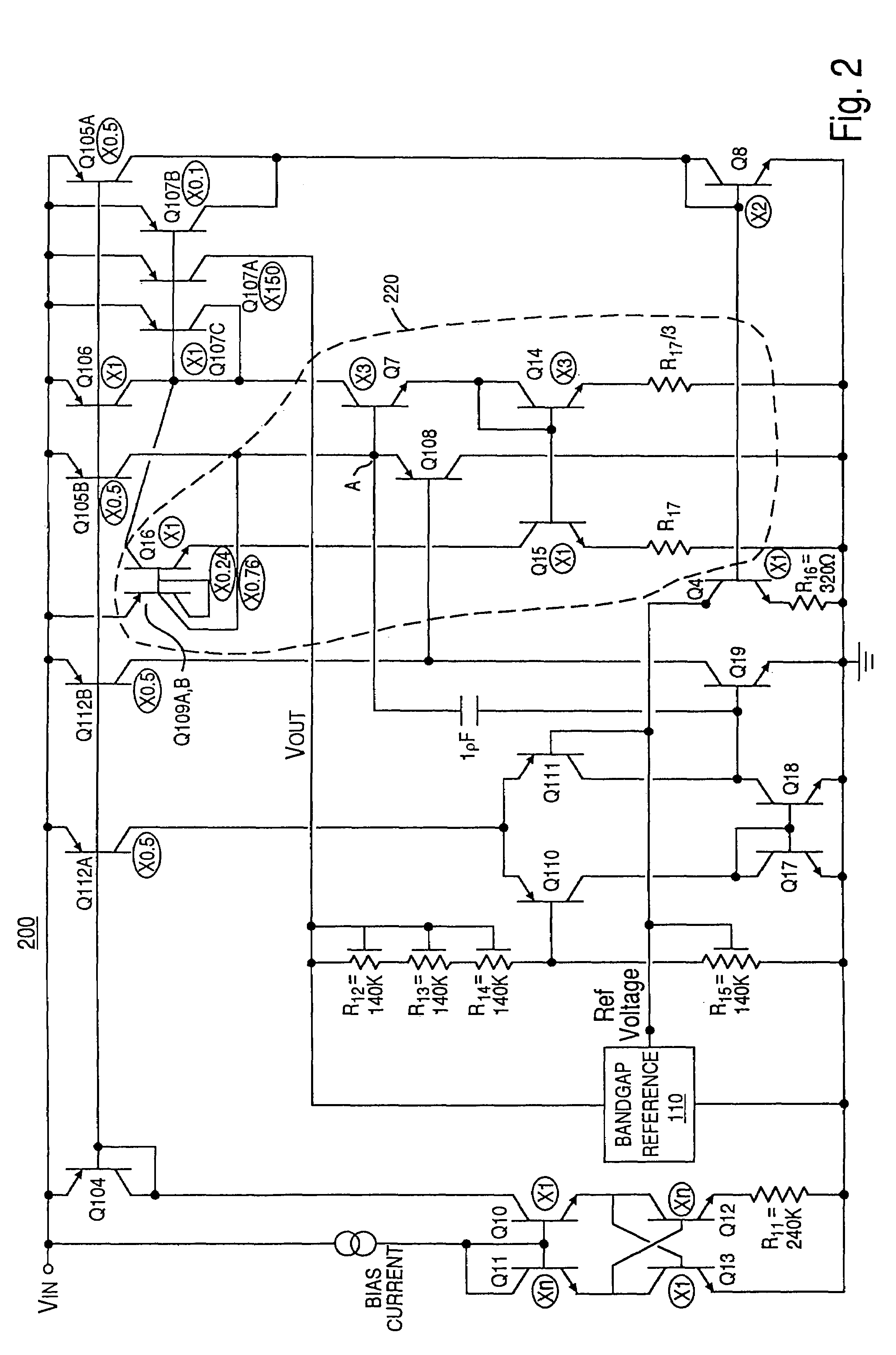
[0010]The drive circuit of the voltage regulation circuit just described may be implemented with field effect devices or bipolar devices, in accordance with different embodiments of the present invention. In one embodiment in accordance with the present invention, the drive circuit of the circuit just described comprises a field effect transistor. In another embodiment in accordance with the drive circuit comprises a first transistor coupled to the output stage, a base current translation circuit, and a current divide circuit coupled to the first transistor and to the base current translation circuit. The current divide circuit is operable to deliver a portion of a first current of the first transistor to the base current translation circuit. Furthermore, the base current translation circuit is operable to delive

Problems solved by technology

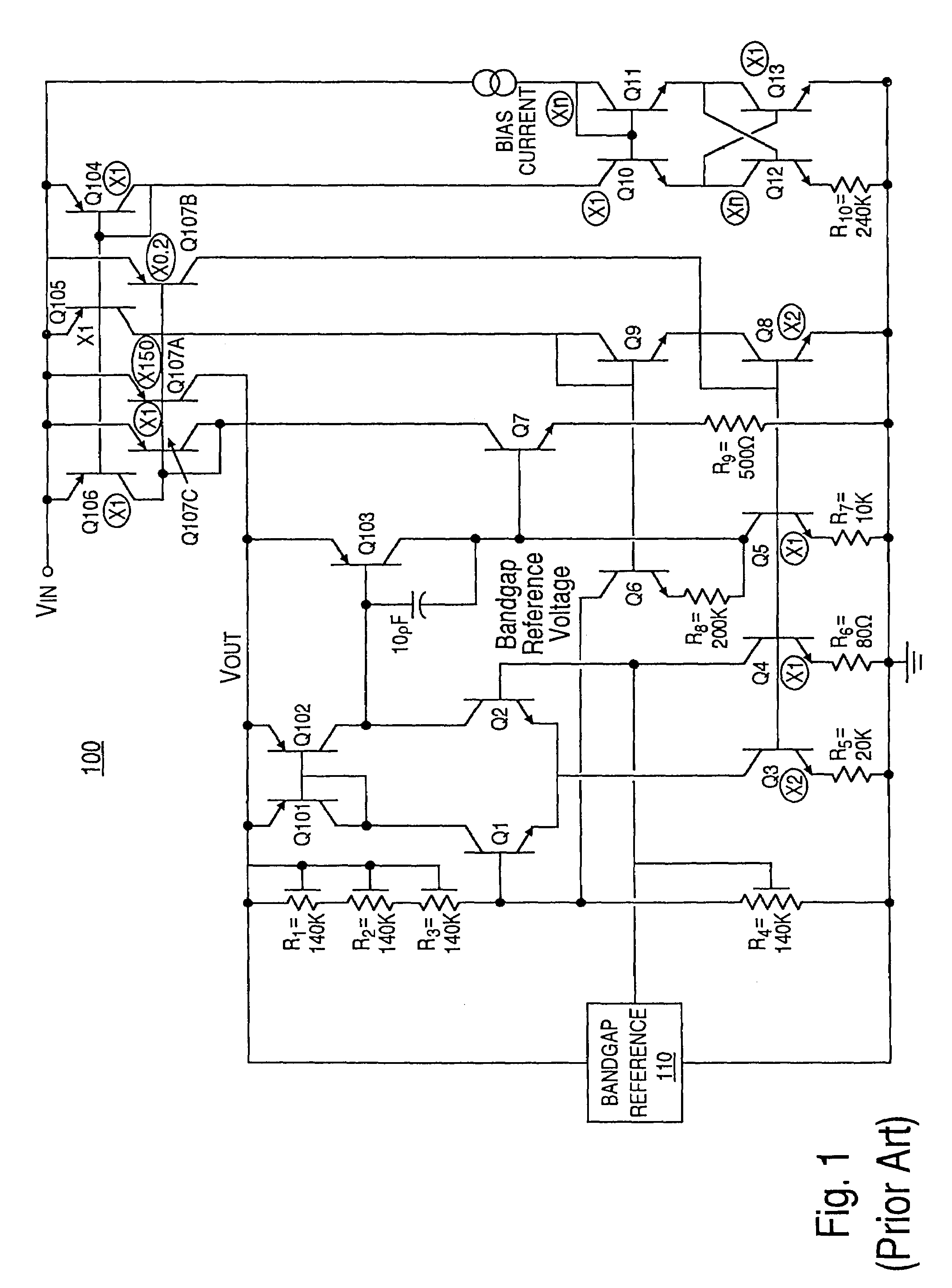
While the conventional difference amplifier illustrated in FIG. 1, as well as other conventional difference amplifiers, are well-suited for a number of applications, they have several limitations.
First, such conventional difference amplifies are often designed to operate over a relatively limited range in output current.
Second, such circuits are often designed to output a single fixed output voltage.
I

Method used


Image

  • Difference amplifier for regulating voltage
  • Difference amplifier for regulating voltage
  • Difference amplifier for regulating voltage

Examples


Embodiment Construction

[0020]Reference will now be made in detail to the preferred embodiments of the invention, examples of which are illustrated in the accompanying drawings. While the invention will be described in conjunction with the preferred embodiments, it will be understood that they are not intended to limit the invention to these embodiments. On the contrary, the invention is intended to cover alternatives, modifications and equivalents, which may be included within the spirit and scope of the invention as defined by the appended claims. Furthermore, in the following detailed description of the present invention, numerous specific details are set forth in order to provide a thorough understanding of the present invention. However, it will be obvious to one of ordinary skill in the art that the present invention may be practiced without these specific details. In other instances, well-known methods, procedures, components, and circuits have not been described in detail as not to unnecessarily ob...


PUM


Abstract

A voltage regulation circuit. The voltage regulator includes an input stage, a reference voltage circuit, a gain stage, and an output stage. The reference voltage circuit is coupled to one input of the input stage, and the output stage is coupled to another input of the input stage. The gain stage includes a buffer device coupled to the output of the input stage and a drive circuit coupled to the output stage. The buffer device is operable to provide isolation between the input stage and the drive circuit. The drive circuit may include a first transistor coupled to the output stage, a base current translation circuit, and a current divide circuit coupled to the first transistor and to said base current translation circuit. The input stage may be biased with a substantially constant bias current, such that output dependent current loading effects are avoided.

Description

TECHNICAL FIELD[0001]The present invention generally pertains to the field of electronic circuits. More particularly, embodiments of the present invention are related to a difference amplifier for regulating a voltage.BACKGROUND ART[0002]Many electronic circuits have a need for a regulated voltage. FIG. 1 illustrates an example of a conventional difference amplifier 100 that may be used to provide a regulated voltage. The difference amplifier 100 of FIG. 1 regulates a voltage (Vout) by using voltage feedback in a loop having a differential pair of transistors. The differential pair compares a reference bandgap voltage with a pre-determined fraction of the output voltage and produces a drive-signal based on the comparison.[0003]The voltage at the input of transistor Q1 is some fraction of the voltage, Vout, based on the relative sizes of the voltage divider resistors R1, R2, R3, and R4. The difference amplifier 100 keeps the voltage, Vout, regulated by forcing the voltage at the inpu...

Claims


Application Information

Patent Timeline
IPC IPC(8): G05F1/567
CPCG05F3/222Y10S323/907
Inventor DOW, RONALD NEAL
Owner NAT SEMICON CORP
Why Eureka
Try Eureka