Antenna unit and portable radio system comprising antenna unit

a portable radio system and antenna unit technology, applied in the direction of resonant antennas, telephone set constructions, radiating element structural forms, etc., can solve the problems of inconvenient user carrying and operating the phone, inability to maintain the physical strength of the antenna, and easy affect of the antenna uni

Inactive Publication Date: 2006-10-24
PANASONIC CORP
View PDF13 Cites 39 Cited by
  • Summary
  • Abstract
  • Description
  • Claims
  • Application Information

AI Technical Summary

Benefits of technology

[0032]According to this configuration, the antenna current is induced in the antenna element at the transmitting frequency, while another antenna current is induced in the parasitic element at the receiving frequency by the spatial coupling between the antenna element and the parasitic element. Therefore, a wider bandwidth can be obtained without provision of a matching circuit and also expansion of a parts packaging space on a board and reduction in the number of packaged parts can be achieved.
[0062]According to this configuration, since any one of above antenna units is provided, the portable radio device having the same advantages as those achieved by the antenna units can be realized.

Problems solved by technology

Meanwhile, according to this telescopic antenna unit, the helical antenna 203 of this antenna unit is always protruded from the housing 201 of the mobile phone 200 to the outside, and thus the presence of such protruded portion causes inconvenience to the user upon carrying and operating the phone.
For this reason, it is possible that the antenna may hit on various things during carried in the rocket, and a physical strength of the antenna cannot be satisfactorily maintained.
However, since this built-in antenna unit is arranged in vicinity of the liquid crystal screen, the board, the speaker, etc. which are constituting the portable radio device, such antenna unit is easily affected by these parts.
Thus, there is a possibility that an increase in the mounting space on the printed board and an increase in the number of articles are brought about.
Also, normally the telescopic antenna unit in the prior art is constructed such that such device is unbalancedly fed to flow the antenna current through the housing of the portable radio device.
In such unbalanced antenna unit, it is known that the antenna gain is degraded by the influence of the user's hand, and so on when the user holds the portable radio device to use.
Thus, there is a possibility of causing an increase of the device in size.
However, there is a possibility that the communication quality in the weak electric field area cannot be kept when the set value is reduced.
Also, in the case of the above conventional telescopic antenna unit, there are the problems that the protrusion of the antenna unit from the portable radio device causes inconvenience upon carrying and operating the phone, and in addition the physical strength cannot be kept.
Also, in the above conventional unbalanced antenna unit, there is the problem that the antenna gain is degraded by the influence of the user's hand when the user holds the portable radio device to use.
Also, in the above conventional portable radio device, there is the disadvantage that the communication quality is degraded in the weak electric field area when the set value of the maximum sending power is decreased to reduce the SAR value.

Method used


Image

  • Antenna unit and portable radio system comprising antenna unit
  • Antenna unit and portable radio system comprising antenna unit
  • Antenna unit and portable radio system comprising antenna unit

Examples


first embodiment

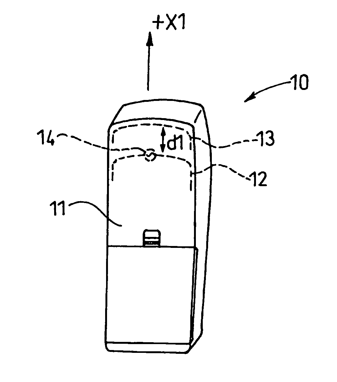
[0080]FIG. 4 is an appearance view of the back surface side of a mobile phone 10 of a W-CDMA (Wideband Code Division Multiple Access) system into which an antenna unit according to a first embodiment of the present invention is incorporated. FIG. 4 shows a perspective view when a not-shown LCD (Liquid Crystal Display) screen and a key portion are arranged to direct toward the back of this sheet. In this case, as with the transmitted / received frequencies in this W-CDMA system, the transmitting frequency is set to 1920 MHz to 1980 MHz and the receiving frequency is set to 2110 MHz to 2170 MHz.

[0081]The mobile phone 10 shown in FIG. 4 has an antenna element 12 and a parasitic element 13 in a rod-like housing 11. For example, a size of this housing 11 has a length of 110 mm in the longitudinal direction, a length of 40 mm in the width direction, and a length of 15 mm in the thickness direction. The LCD and the key portion, although not shown, are arranged on an upper portion and a lower...

second embodiment

[0101]FIG. 5 is a perspective appearance view showing a mobile phone 20 corresponding to a particular communication system into which an antenna unit according to a second embodiment of the present invention is incorporated. In this case, in this embodiment, the same reference symbols are affixed to the same portions as those in the first embodiment and their duplicate explanation will be avoided herein.

[0102]The mobile phone 20 in the present embodiment has the same basic configuration as that of the mobile phone 10 shown in FIG. 4 in the first embodiment. As the communication system used herein, for example, the receiving frequency of 2300 MHz to 2350 MHz and the transmitting frequency of 2400 MHz to 2450 MHz are employed respectively and the receiving frequency is set lower than the transmitting frequency conversely to the first embodiment.

[0103]The mobile phone 20 shown in FIG. 5 has an antenna element 22 and a parasitic element 23 in the rod-like housing 11. A size of the housi...

third embodiment

[0114]FIG. 6 is an appearance view of a mobile phone 30 of the W-CDMA system into which an antenna unit according to a third embodiment is incorporated. In this case, in this embodiment, the same reference symbols are affixed to the same portions as those in the first embodiment and their duplicate explanation will be avoided herein.

[0115]The mobile phone 30 shown in FIG. 6 has the same basic configuration as the mobile phone 10 in the first embodiment, and has an antenna element 32 and a parasitic element 33 in the rod-like housing 11. Also, in the mobile phone 30 in the present embodiment, a length in the longitudinal direction of the housing 11 is 110 mm, a length in the width direction is 40 mm, and a length in the thickness direction is 15 mm. As with the transmitting / receiving frequencies in this W-CDMA system, as described in the first embodiment, the transmitting frequency is 1920 MHz to 1980 MHz while the receiving frequency is 2110 MHz to 2170 MHz.

[0116]In the antenna unit...


PUM


Abstract

A subject of the present invention is to provide an antenna unit and a portable radio device capable of attaining a wider bandwidth and a lower SAR.In the present invention, an antenna element (12) that has an effective length corresponding to a half wavelength of a transmitting frequency and a parasitic element (13) that has an effective length corresponding to a half wavelength of a receiving frequency are provided, an antenna current is induced in the antenna element (12) at the transmitting frequency upon transmitting a radio wave in a predetermined transmitting frequency band, and another antenna current is induced in the parasitic element (13) by a spatial coupling between the antenna element (12) and the parasitic element (13) at the receiving frequency upon receiving the radio wave in a predetermined receiving frequency band, whereby peak points in an antenna current distribution are scattered into two points. Accordingly, a wider bandwidth can be obtained without addition of a matching circuit and also expansion of a parts packaging space on a board and reduction in the number of packaged parts can be achieved.

Description

[0001]This application is a 371 of PCT / JP03 / 01575 filed on Feb. 14, 2003.TECHNICAL FIELD[0002]The present invention relates to an antenna unit used in a portable radio device and a portable radio device equipped with this antenna unit.BACKGROUND ART[0003]The mobile radio communication system recently spreads. In the portable radio device, or the like, for example, the user anticipates further reduction in size, weight and cost of the device. Also, the portable radio device capable of meeting a plurality of communication systems that make transmission / reception in a plurality of different frequency bands is now investigated. Thus, the user expects the device to handle the frequency bands of a plurality of communication systems by one antenna unit. As a result, a smaller size, a lower cost attained by the reduction in the number of articles and the assembling man-hours, or a wider frequency characteristic to be secured, and so forth are required of the antenna unit that is incorporate...

Claims


Application Information

Patent Timeline
Patent Type & Authority Patents(United States)
IPC IPC(8): H01Q1/24H01Q19/28H01Q1/36H01Q1/38H01Q9/04H01Q9/16H01Q19/00H01Q19/30H04B7/26H04M1/02
CPCH01Q1/243H01Q1/36H01Q9/04H01Q9/16H01Q19/005H01Q19/30H01Q1/242
Inventor NAGANO, KENYAOGA, TADASHI
Owner PANASONIC CORP
Why Eureka
Try Eureka