Video conferencing device and method

a video conferencing and video conferencing technology, applied in the field of video conferencing devices and methods, can solve the problems of inability to fully utilize video conferencing, inability to make eye contact, and inability to meet the eye, so as to achieve the effect of promoting the sense of direct eye conta

Inactive Publication Date: 2006-10-24
LEWIS THOMAS B +1
View PDF20 Cites 61 Cited by
  • Summary
  • Abstract
  • Description
  • Claims
  • Application Information

AI Technical Summary

Benefits of technology

[0014]The present invention is directed towards a method of video conferencing and apparatus useful in carrying out the recited method. Each remote conference location is provided with a video conferee, a video camera and an image monitor, wherein each monitor displays an image of the remote conferee. The video camera in each location is placed proximate its associated video monitor and is positioned at an emotionally neutral field of the image of the remote conferee as appearing upon the video monitor. Ideally, the optical axis of each video camera is aimed at the eyes of the conferee facing the video monitor at an angle that promotes the sense of direct eye contact between conferees.

Problems solved by technology

Although video teleconferencing offers an attractive alternative to face-to-face meetings, its adoption has not been as pervasive as predicted.
However, the ergonomics inherent in video conferencing to date have limited its application.
Unfortunately, video teleconferencing involves an inherent lack of eye contact as part of the overall conferencing experience.
Without suitable eye contact, the potential of video conferencing is greatly reduced.
However, such a configuration does not enable the camera lens to extend far enough within the image to reduce the parallax angle a sufficient amount to cure the problem.
In addition, the camera housing clearly obstructs the image field and detracts from the video conferencing experience.
However, these approaches require bulky equipment and are distracting in presenting a certain amount of visual obstruction.
Such devices are necessarily large and cumbersome.
Moreover, because the conferee cannot see the camera filming the event, the conferee never actually looks at the camera, but merely in the general direction of the eyes of the remote conferee.
This approach is obviously hardware and software intensive and is thus expensive to construct and employ and thus somewhat impractical.

Method used


Image

  • Video conferencing device and method
  • Video conferencing device and method
  • Video conferencing device and method

Examples


Embodiment Construction

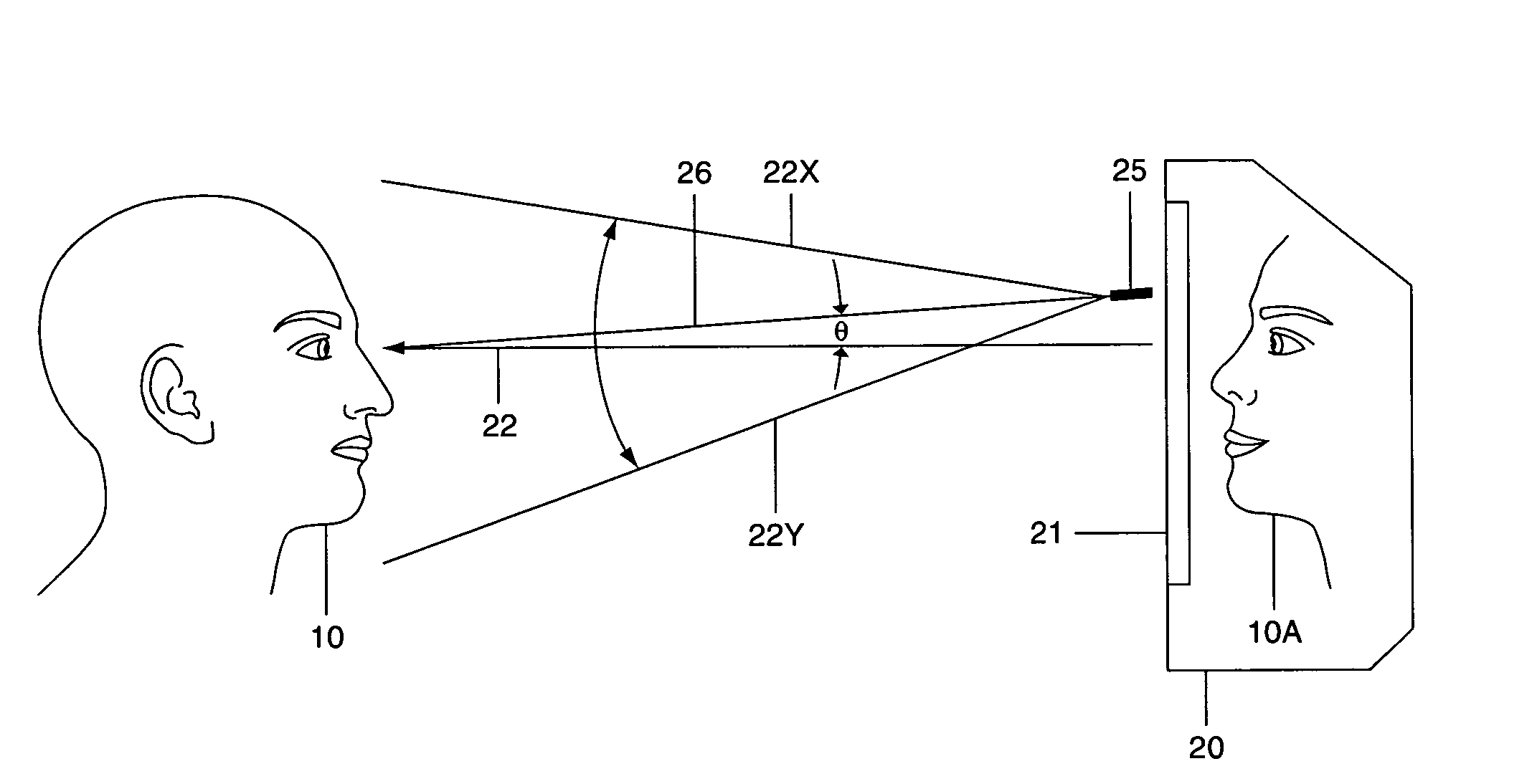
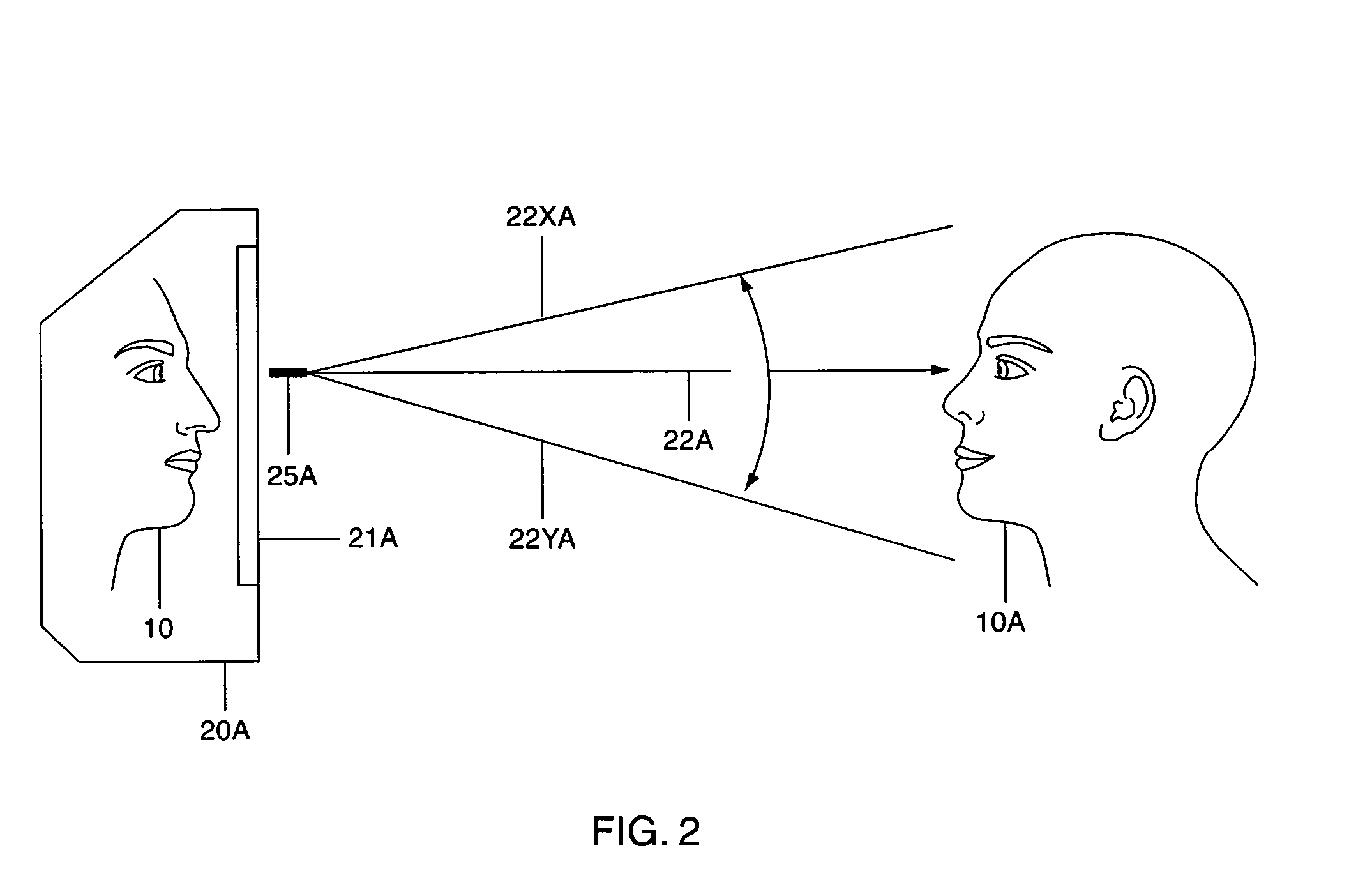
[0022]In maximizing eye contact, reference is made to FIG. 2. Conferee 10 is ideally seated from 2 to 8 feet from video monitor 20 and particularly, its front face carrying image field 21 displaying the image of remotely located conferee 10a. To maximize direct eye contact, FIG. 2, shows camera 25 on or proximate to image field 21 at the eye level of conferees 10 and 10A. Stated differently, video camera 25 is placed in front of monitor 20 within image field 21 whereby its optical axis coincides with the sight line 22 drawn between the eyes of the respective conferees. The camera's field of view is shown by phantom lines 22A and 22B and is adjusted and the conferees positioned so that the size of the facial image as it appears on the monitor at the remote location is approximately the same size as it would be if the conferee was attending a conference physically. However, as the prior art well recognized, placing camera 25 in front of the eyes of an image of the remote conferee with...


PUM


Abstract

A method and device for video conferencing between first and second conference locations. Each conference location is provided with a video camera and a video image monitor to carry the image of a video conferee to a remote location. The video cameras are located proximate the video monitors such that each video camera is placed upon an emotionally neutral field of the image of the remotely located conferee and aimed substantially at the eyes of the local conferee facing the conferee's monitor in order to create eye-to-eye contact between conferees while positioning the video camera as to not interfere with said conference.

Description

TECHNICAL FIELD[0001]The present invention is involved with a method and device for video conferencing between remote conference locations. The device consists of a video camera and image receiver, the image receiver being provided with a border and within the border, an image field for displaying the video image from the remote location. The video camera is mounted within the image field such as to promote eye-to-eye contact between conferees without camera intrusion.BACKGROUND OF THE INVENTION[0002]Although video teleconferencing offers an attractive alternative to face-to-face meetings, its adoption has not been as pervasive as predicted. Certainly with the cost and inconvenience of air travel, being able to conduct conferences through electronic video conferencing provides a low cost and convenient alternative. However, the ergonomics inherent in video conferencing to date have limited its application.[0003]It is well known that in addition to what is said at a meeting, emotiona...

Claims


Application Information

Patent Timeline
Patent Type & Authority Patents(United States)
IPC IPC(8): H04N7/14
CPCH04N7/144
Inventor LEWIS, THOMAS B.MEIXEL, GEORGE
Owner LEWIS THOMAS B
Why Eureka
Try Eureka