Optical disk apparatus and method for adjusting optical disk apparatus laser power

Inactive Publication Date: 2006-10-24
SHARP KK
View PDF13 Cites 4 Cited by
  • Summary
  • Abstract
  • Description
  • Claims
  • Application Information

AI Technical Summary

Benefits of technology

[0018]According to the invention, detection means permits detection of an amount of change in a factor causing fluctuation in effective power as necessary during recording or readout. Furthermore, control means makes it possible to cause a laser to be emitted from a laser source such that it has an optimum emitted power based on the amount of the change obtained and based on compensation data stored at storage means. This makes it possible to eliminate the effects of factors causing fluctuation in effective power and ensure that the effective power of a laser irradiating an active layer will always be maintained at an optimum laser power.
[0035]Furthermore, in accordance with the invention, measurement of an amount of a change in a factor causing fluctuation in effective power as necessary during recording or readout permits optimum emitted power to be controlled at each occurrence of a change in a factor causing fluctuation in effective power, permits elimination of effects of factors causing fluctuation in effective laser power, and makes it possible to ensure that the effective power of a laser irradiating an active layer will always be maintained at an optimum laser power. As a result, it is possible to obtain satisfactory signal quality during readout and achieve increases in the density with which signals are recorded at an active layer.

Problems solved by technology

As a result, even for the same apparatus-disk combination and even where temperature is held constant, optimum laser power will in general in such a case be nonconstant due to varying conditions at the apparatus, resulting in the problem that it is difficult to cause the laser to irradiate the disk active layer with optimum laser power.
Accordingly, despite use of APC (Automatic Power Control) to maintain a constant laser power emitted from the laser source, the laser power exiting the objective lens will nonetheless fluctuate, making it impossible to irradiate the disk active layer with constant effective power.
Another cause of objective lens shift is lag in tracking during seek servo operations for moving the optical head in the radial direction of the disk.
For these and other reasons, occurrence of objective lens shift is unavoidable.
That is, there is an error component due to fluctuation in laser power caused by objective lens shift which is in general present despite the fact that the laser power exiting the laser source at the time of recording is an optimum laser power as determined by carrying out a test write.
Accordingly, as conventional optical disk apparatuses do not permit compensation for variation in optimum laser power due to changes in objective lens shift and other such factors causing fluctuation in effective power, there is the problem that recording is carried out at a laser power other than the optimum laser power at the time of recording, causing decrease in readout signal quality.

Method used


Image

  • Optical disk apparatus and method for adjusting optical disk apparatus laser power
  • Optical disk apparatus and method for adjusting optical disk apparatus laser power
  • Optical disk apparatus and method for adjusting optical disk apparatus laser power

Examples


Embodiment Construction

[0043]Now referring to the drawings, preferred embodiments of the invention are described below.

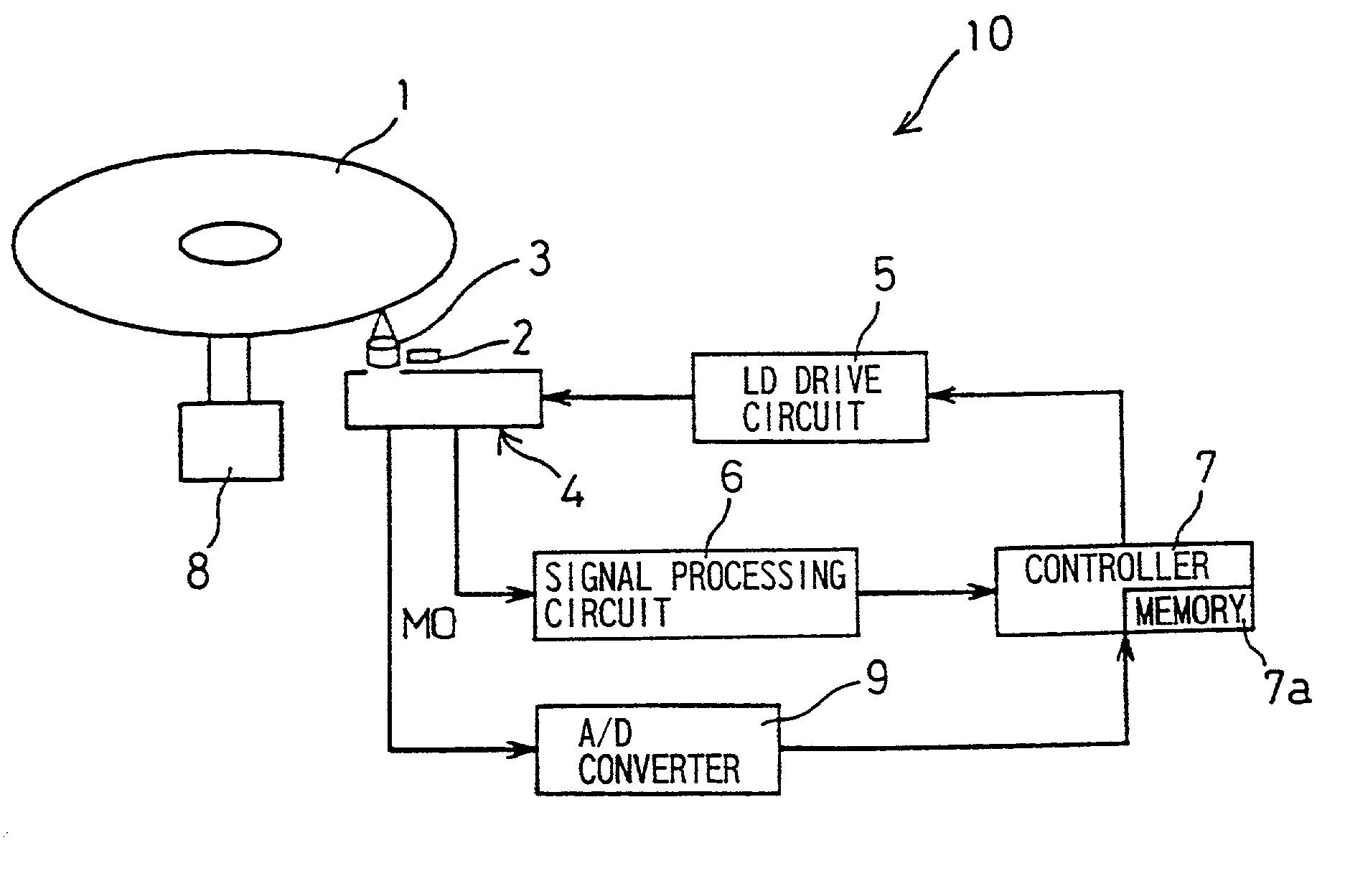
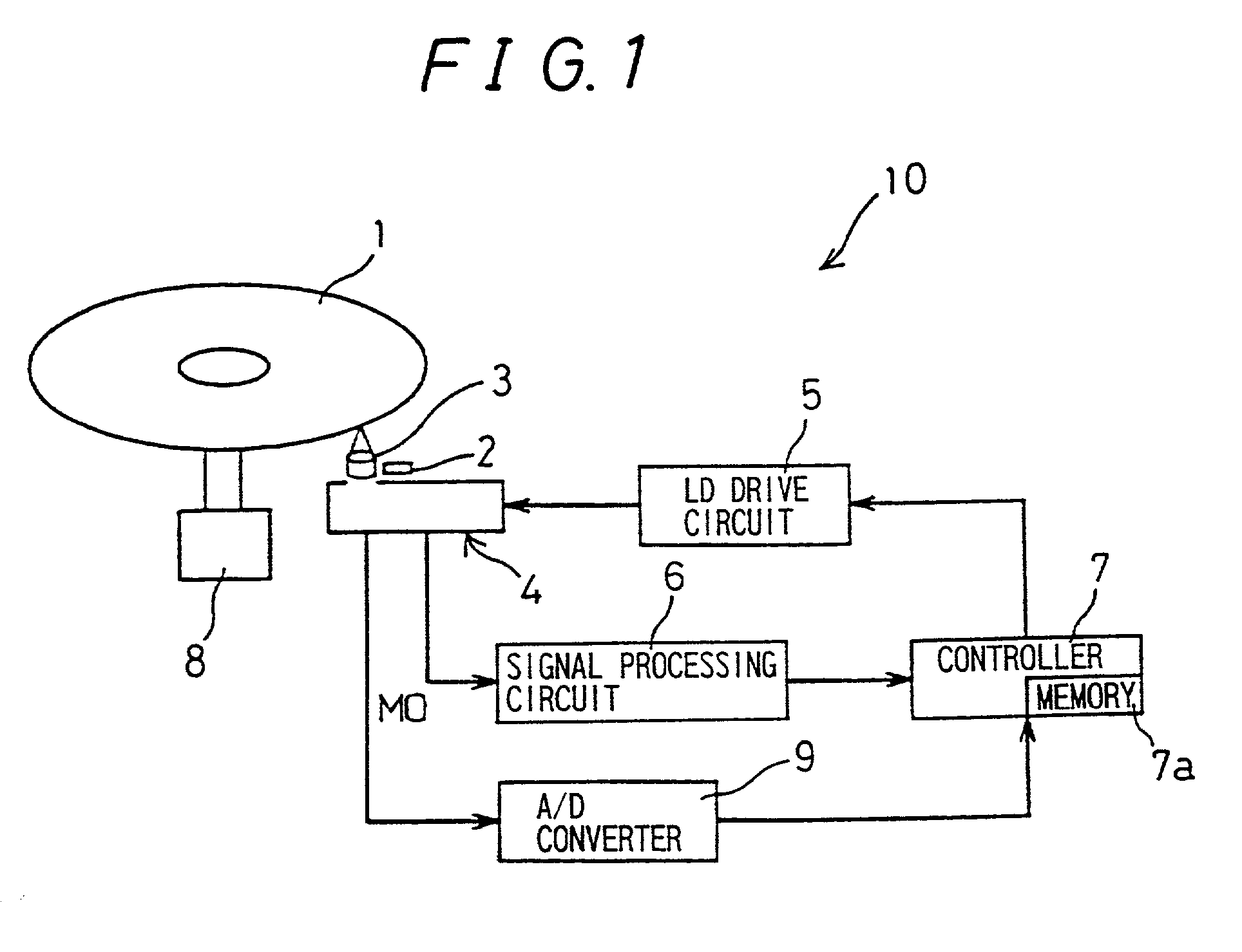
[0044]FIG. 1 is a block diagram showing the principal components of an optical disk apparatus 10 in one embodiment of the invention. The optical disk apparatus 10 is capable of causing recording to and readout from an optical disk, and the present embodiment is described in terms of an optical disk apparatus employing magneto-optical recording.

[0045]The optical disk apparatus 10 irradiates the active layer of an optical disk 1 with a laser emitted from a laser source internal to a head 4, and light reflected from the active layer of the optical disk 1 is incident on a photodetector of the head 4, where it is converted to a data signal, permitting readout of data recorded on the optical disk 1. Furthermore, by adjusting the power of the laser irradiating the active layer of the optical disk 1 it is possible to alter the state of the active layer at the optical disk 1, permitting data to be...


PUM


Abstract

Provision of a displacement sensor, which detects an amount of shift at an objective lens, and a controller, which adjusts an emitted power based on a value measured by the displacement sensor and compensation data stored in a memory, permits detection by the displacement sensor of the amount of shift at the objective lens as necessary during recording of data, and the controller is capable of causing emission of an optimum emitted power from a laser source to an optical disk based on the measured value obtained and the compensation data. As a result, elimination of effects of fluctuation in effective power due to objective lens shift is permitted, and it is possible to ensure that the effective power of a laser irradiating the active layer will always be maintained at an optimum laser power.

Description

BACKGROUND OF THE INVENTION[0001]1. Field of the Invention[0002]The invention relates to an optical disk apparatus and a method for adjusting optical disk apparatus laser power, and relates in particular to an optical disk apparatus and a method for adjusting optical disk apparatus laser power, permitting compensation for factors causing fluctuation in effective power.[0003]2. Description of the Related Art[0004]In recent years, with the digitalization of video data, audio data, and various other types of data, there has been a dramatic increase in digital data volume. Accompanying this, development of optical disk apparatuses suited for high-capacity, high-density applications has proceeded apace. Along with progress in achieving increased density in optical disk apparatuses there has been decreased signal quality in the readout signal, and there have been a great many inventions proposing various methods for obtaining satisfactory signal quality. The factors affecting the signal q...

Claims


Application Information

Patent Timeline
IPC IPC(8): G11B19/00G11B7/004G11B15/52G11B7/00G11B7/0045G11B7/085G11B7/125G11B7/126
CPCG11B7/0045G11B7/126G11B7/00G11B7/085G11B7/004
Inventor AKIYAMA, JUN
Owner SHARP KK
Why Eureka
Try Eureka