
Method and system for compensating for side effects of cross gain modulation in amplified optical networks

a technology of cross gain modulation and amplified optical networks, applied in the field of fiber optic networks, can solve the problems of compromising the accuracy of channel identification in optical networks, increasing the task of network management, and difficulty in identifying channels down stream of such amplification points in the network, so as to reduce the effect of obviating shortcomings

Inactive Publication Date: 2006-10-24
WSOU INVESTMENTS LLC +1
View PDF0 Cites 9 Cited by
  • Summary
  • Abstract
  • Description
  • Claims
  • Application Information

AI Technical Summary

Benefits of technology

[0023]Therefore there is an object of the invention to provide an improved method and system which would compensate for side effects of cross gain modulation in amplified optical networks, thus reducing and / or obviating shortcomings of the prior art.
[0044]The embodiments of the invention provide a system and method to effectively deal with the side effects of XGM to identify between expected and unexpected channels in the optical network. Due to the use of the dynamic unexpected tone threshold, which adapts automatically to the level of the actual valid tones of the expected channels, such identification becomes more robust, thus enabling more accurate channel identification in optical networks.

Problems solved by technology

As communications networks become more complex, the task of network management becomes increasingly difficult.
Faults in the optical switching and transmission equipment that make up the network may have the effects of disrupting the transmission of a channel, or switching it incorrectly.
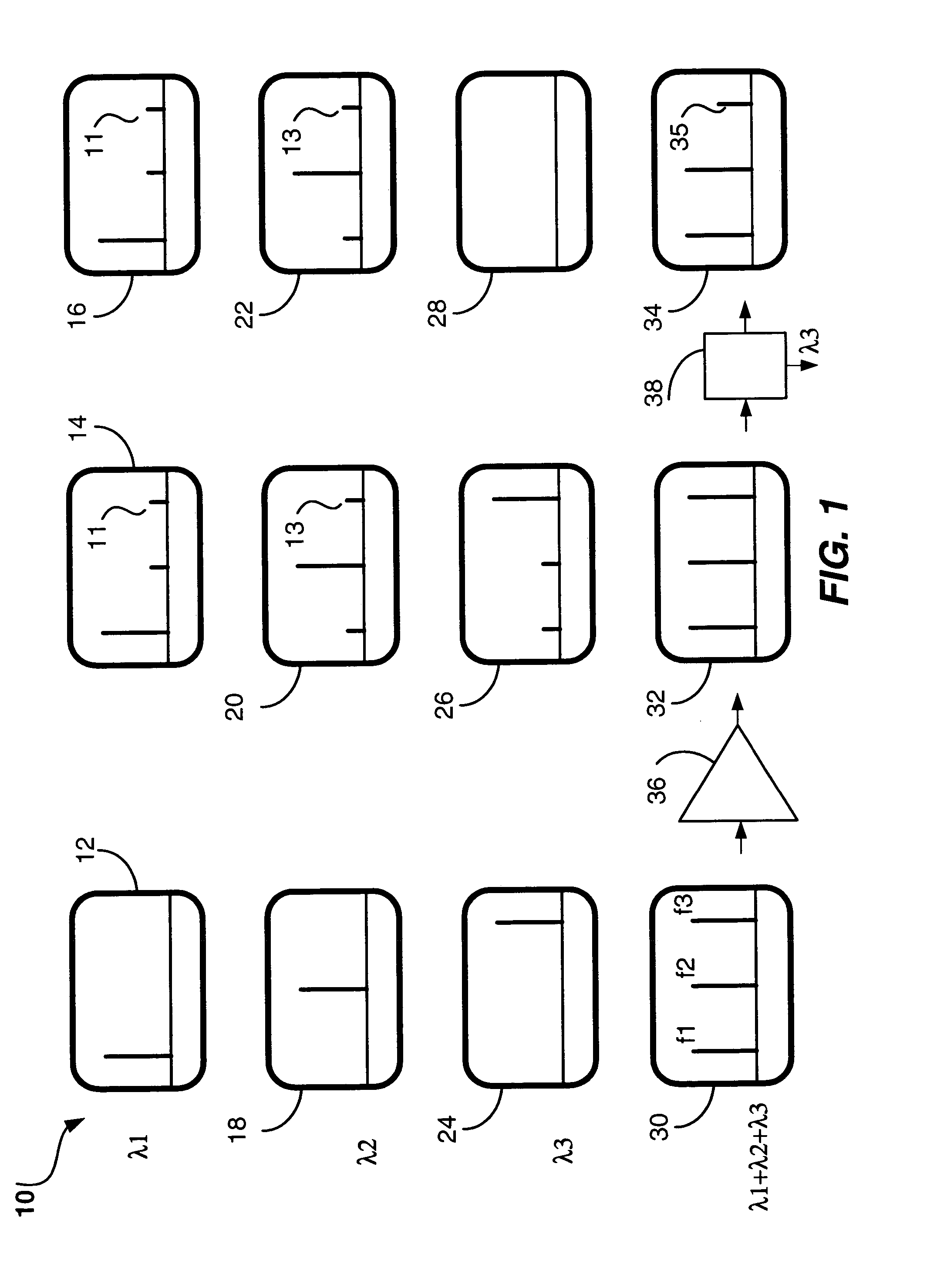
As a result of this cross talk, the identification of channels down stream of such amplification points in the network is rendered more difficult, because the tones constituting a channel signature belonging to a particular wavelength channel may also appear (in attenuated form) on other channels.
Thus, the presence of ghost tones due to XGM may compromise the accuracy of channel identification in optical networks, especially larger optical networks with many optical amplifiers, and networks with a large number of wavelength channels and a large number of tones, including networks using multiple tones as channel signatures.

Method used


Image

  • Method and system for compensating for side effects of cross gain modulation in amplified optical networks
  • Method and system for compensating for side effects of cross gain modulation in amplified optical networks
  • Method and system for compensating for side effects of cross gain modulation in amplified optical networks

Examples


first embodiment

[0064]The general formula used in computing the dynamic unexpected tone threshold “TU” is as follows:

[0065]T⁢⁢U=10·log⁡(∑i=1Z⁢⁢Vi·Ei)-OFFSET(1)

[0066]where i=1 to Z, Vi is the measured amplitude of the i-th valid tone,

[0067]Ei is the number of EDFA amplifiers in the path of the i-th valid tone, and

[0068]Z is the number of valid tones.

[0069]The value of OFFSET depends on the frequency range of the tones used in channel signatures, and on the characteristics of the EDFA amplifiers used. In the network of the preferred embodiment the value of OFFSET is 32 dB, based on a range of tone frequencies (“tonespace” in the US application to Obeda cited above) from about 48 kHz to about 64 kHz, and the XGM characteristics of amplifiers, e.g., from different manufacturers, or employing different control mechanisms.

second embodiment

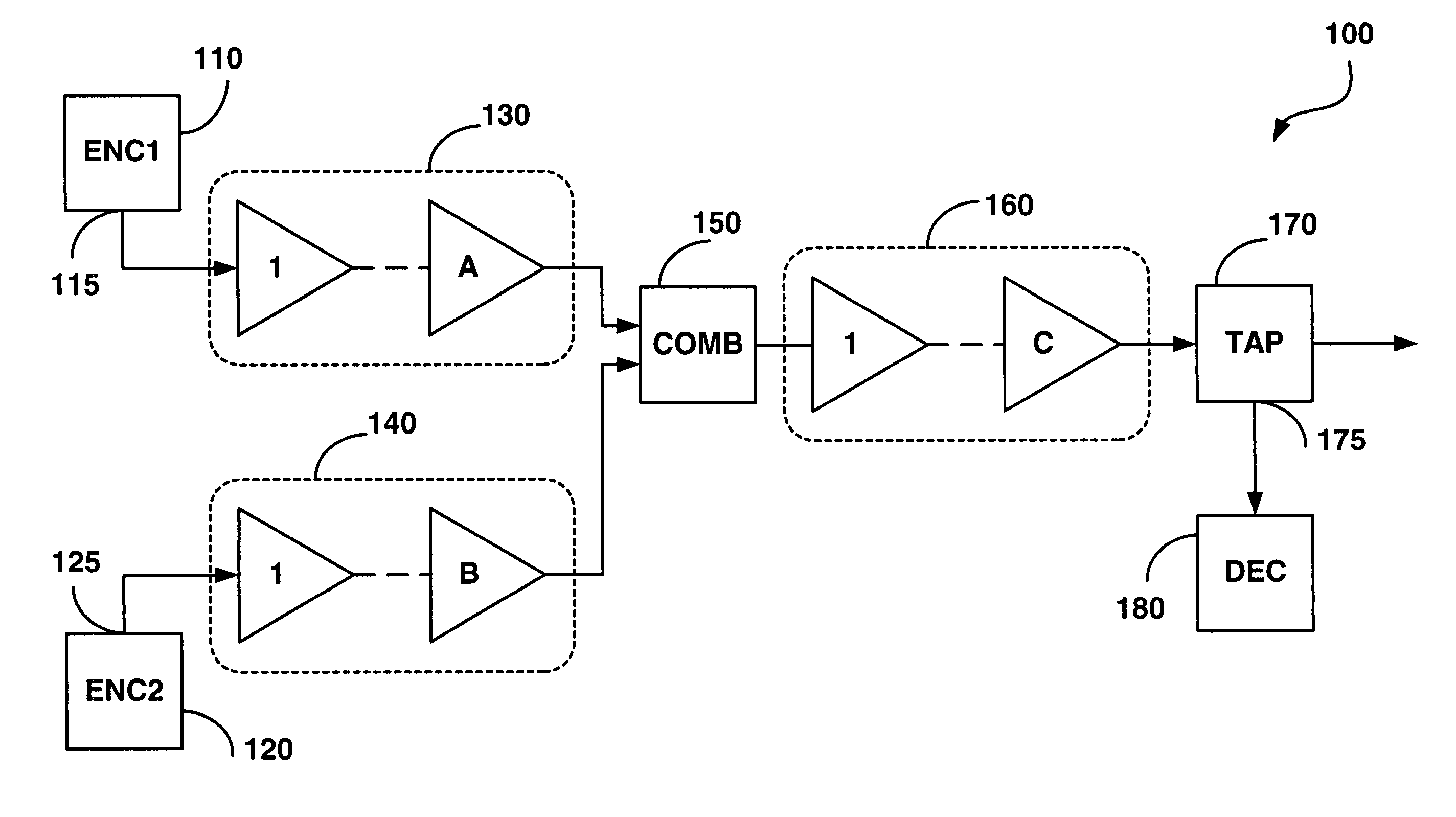
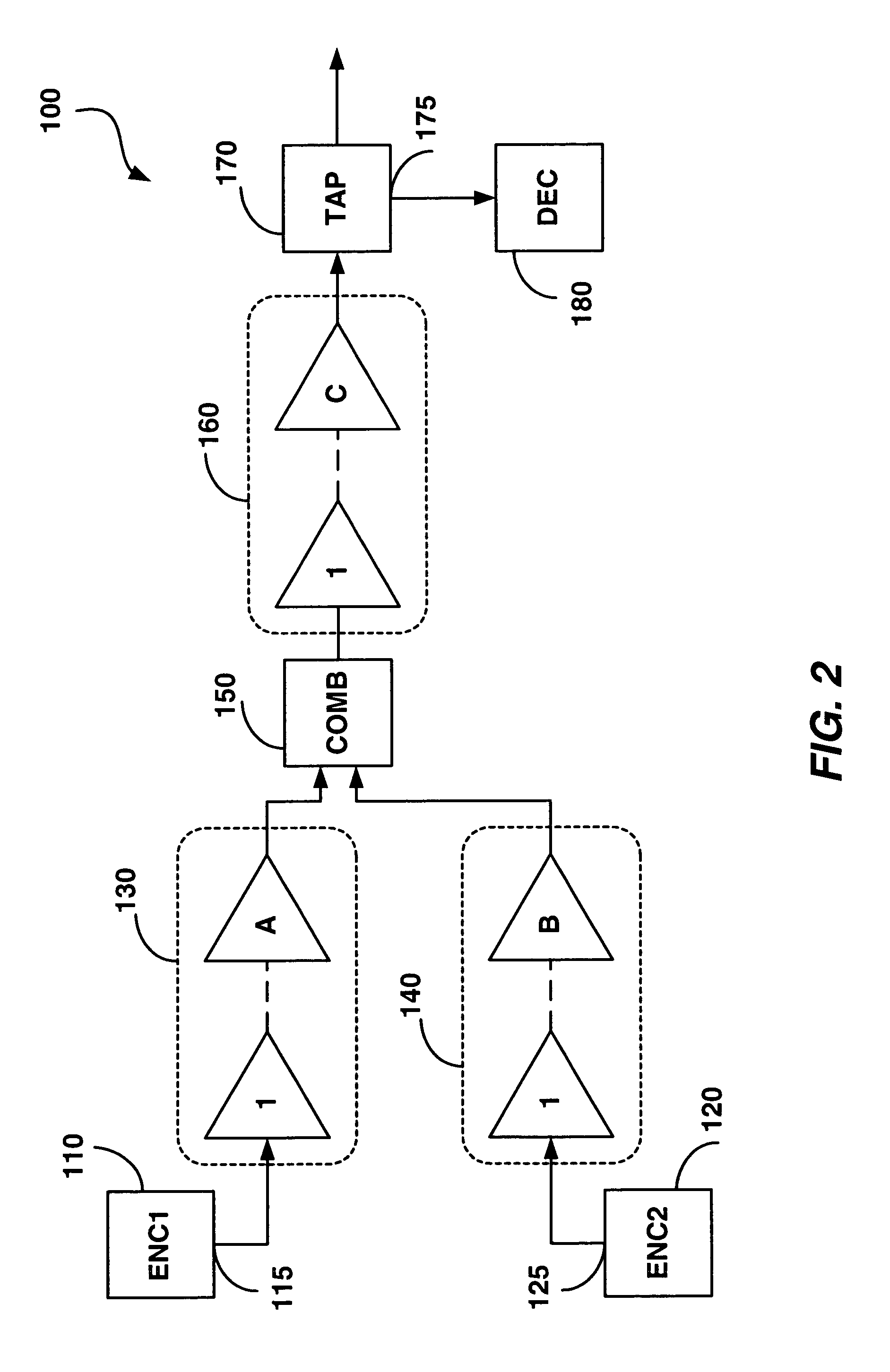
[0070]In the second embodiment, the formula (1) is being adapted to become more efficient for computation of the unexpected tone threshold in such cases as the example network of FIG. 2, where there are a small number of groups of channels from multi-channel sources (ENC1 and ENC2), and where there are chains of amplifiers common to groups of channels.

[0071]The unexpected tone threshold of the decoder 180 of the network 100 in FIG. 2, using the preferred value for OFFSET, may be calculated as follows:

[0072]T⁢⁢U=10·log⁡(∑i=1ZM⁢⁢Vi·(A+C)+∑j=1ZN⁢⁢Vj·(B+C))-32(2)

[0073]where i=1 to ZM, j=1 to ZN,

[0074]ZM is the number of valid tones corresponding to the channel signatures of the M wavelength channels from the encoder ENC1110; and

[0075]ZN=the number of valid tones corresponding to the channel signatures of the N wavelength channels from the encoder ENC2120.

[0076]The step 250 of determining the presence of unexpected channel signatures includes comparing all other remaining tone amplitudes...


PUM


Abstract

A method and system for compensating for side effects of cross gain modulation in amplified optical networks, which allows reliable identification of expected and unexpected channels in the network is provided. Each optical channel traveling in the optical network is marked with a unique channel signature (expected channel signature), having one or more dither tone modulated onto the optical channel; followed by detecting a spectrum of tones, including said modulated dither tones and ghost tones thereof produced by the cross gain modulation in the optical network, at various locations in the optical network. Amplitudes of the spectrum tones, which belong to the expected channel signature, are compared with a first threshold, while amplitudes of the remaining spectrum tones, which are not the valid tones, are compared with a second threshold, which is lower than the first threshold. The spectrum tones are identified as valid tones if their amplitudes are above the first threshold; and an alarm signaling that the expected channel signature is missing is generated if the amplitude of the spectrum tone is below the first threshold. Yet another alarm is generated signaling that an unexpected channel is detected in the network if the amplitude of at least one of the remaining spectrum tones is exceeding the second threshold. Alternatively, the other alarm is generated if amplitudes of the remaining spectrum tones belonging to one of the allowable channel signatures in the network are above the second threshold. A corresponding system incorporating the step of the methods described above is also provided.

Description

RELATED APPLICATION[0001]This application claims benefit from U.S. Provisional Patent Application Ser. No. 60 / 447,726 to Obeda, P. D., et al, entitled “Method and Apparatus for Compensating for Side Effects of Cross Gain Modulation in Amplified Optical Networks”, and filed on 19 Feb. 2003.FIELD OF THE INVENTION[0002]The invention relates to fiber optic networks, and in particular, to method and system for compensating for side effects of cross gain modulation in amplified optical networks.BACKGROUND OF THE INVENTION[0003]As communications networks become more complex, the task of network management becomes increasingly difficult. An important aspect of network management is an identification and accurate record of optical channels in the network, and knowledge of the allocation of channels to the network elements, e.g., to optical links. This may involve knowledge of the allocation of channels to respective optical fibers and optical band filters within the nodes.[0004]One of the co...

Claims


Application Information

Patent Timeline
Patent Type & Authority Patents(United States)
IPC IPC(8): H04B10/08H01S3/00H04B10/18
CPCH04B10/079H04B10/07955H04B2210/075
Inventor OBEDA, PAUL DAVIDBIERMAN, ROBERT MICHAELBACQUE, JAMES BENSONKELLY, COLIN GEOFFREYREMEDIOS, DERRICKWAN, PING WAI
Owner WSOU INVESTMENTS LLC
Learn More