Combustion engine

a combustion engine and combustion chamber technology, applied in the field of combustion engines, can solve problems such as limiting the maximum number of recesses in practice, and achieve the effects of low thermal and acoustic environmental impact and high efficiency

Inactive Publication Date: 2006-10-31
ROELOFS JOHANNES
View PDF11 Cites 2 Cited by
  • Summary
  • Abstract
  • Description
  • Claims
  • Application Information

AI Technical Summary

Benefits of technology

[0006]According to a practical preferred embodiment, the chamber is assembled from three cylinders, the axes of which run substantially parallel to each other. The cross-section of a first part of the chamber preferably takes the form of a first circle with the first rotation axis as centre and a radius which is approximately equal to the radial dimensions of the largest of the associated vanes. The cross-section of a second part of the chamber preferably takes the form of a second circle with the second rotation axis as centre and a radius which is approximately equal to the radial dimensions of the largest of the associated vanes. By varying the position of the rotation axes and the length of the vanes, the volumes of the compartments can be optimally adjusted, and therewith also the ratio between the “intake stroke” compartment and the “power stroke” compartment. As a consequence hereof a higher efficiency can be achieved at a lower exhaust gas temperature and a lower exhaust gas pressure, which causes a low thermal and acoustic environmental impact.

Problems solved by technology

Technical possibilities and cost considerations will however limit the maximum number of recesses in practice.

Method used


Image

  • Combustion engine
  • Combustion engine
  • Combustion engine

Examples


Embodiment Construction

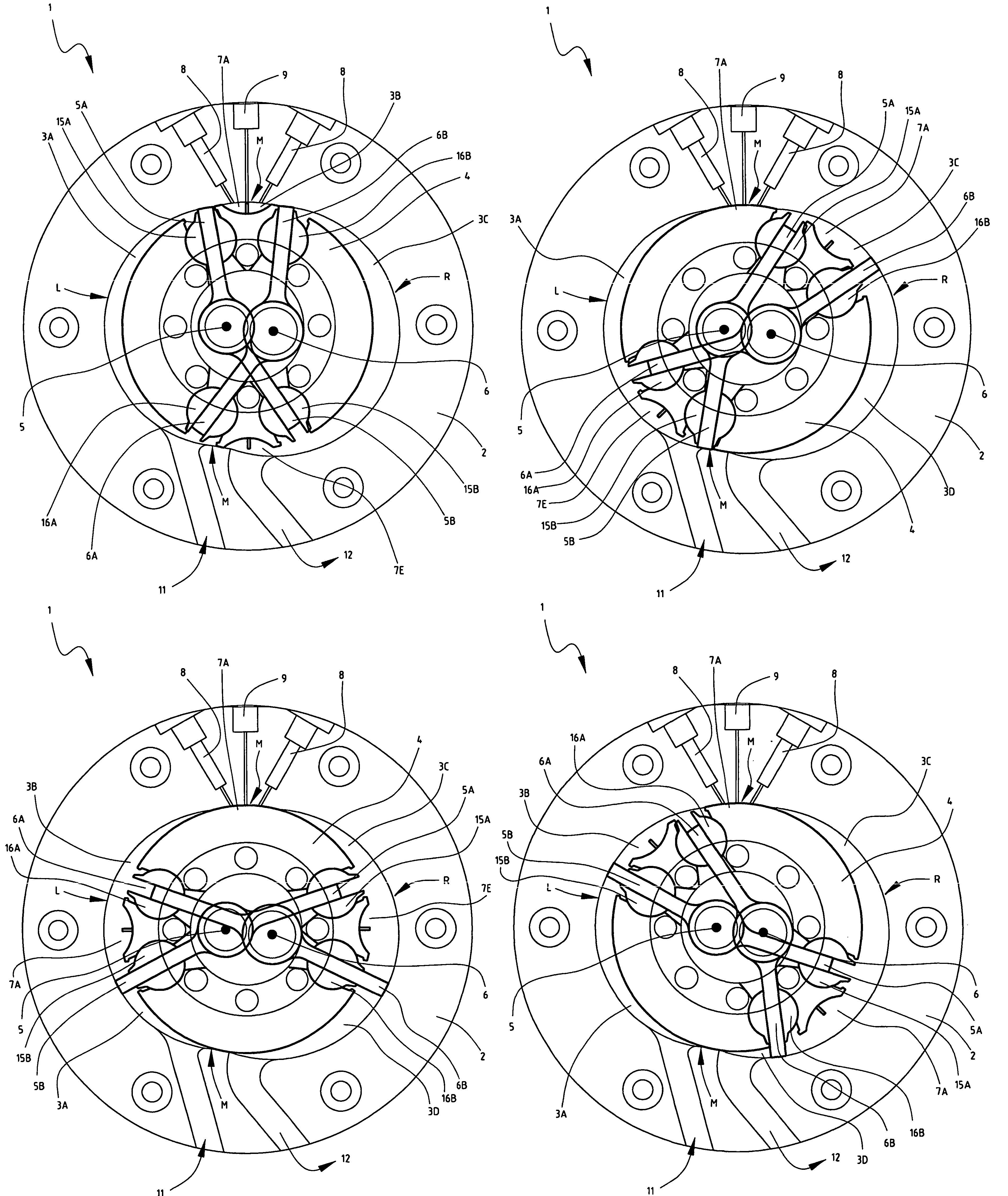
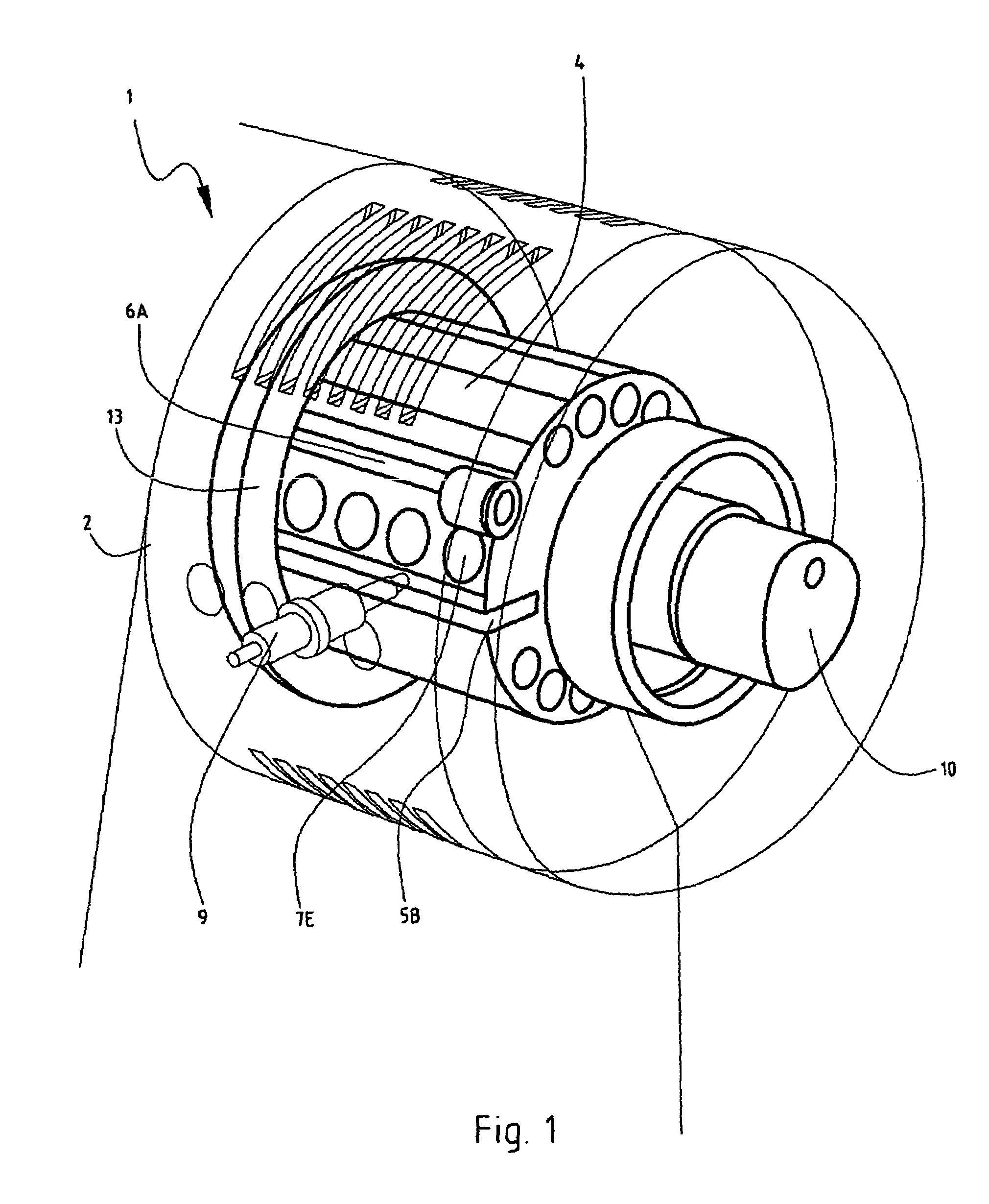
[0020]FIG. 1 shows a schematic view of a preferred embodiment of combustion engine 1 according to the invention. Combustion engine 1 has a housing 2, in which is situated a space or chamber 3. Arranged in chamber 3 is a rotor 4, on which are mounted vanes or blades 5A, 5B, 6A, 6B. The four vanes divide the chamber into a number of compartments. Housing 2, chamber 3 and rotor 4 have a general cylindrical shape.

[0021]Rotor 4 has a number of recesses 7A–H for receiving fuel. The recesses are arranged on either side of the rotor and can take different forms. The form is generally cup-shaped or groove-shaped. An example of a cup shape is a hemisphere or a bowl with an elliptic section resembling half an egg. An example of a groove-shaped form is a half-cylinder. Shown in FIG. 1 by way of illustration are hemispherical recesses 7A–D. The number of recesses 7 amounts to two or more per side and depends on the engine capacity. For illustrative purposes, it is expected that a number of betwe...


PUM


Abstract

The invention relates to a combustion engine (1) having a housing (2) with a chamber (3). A rotor (4) is arranged herein which is provided with a number of vanes (5A, 5B, 6A, 6B) which divide the chamber into a number of compartments (3A, 3B, 3C, 3D). Each of the compartments is intended for performing at least one of the following functions: a) drawing in and/or compressing gas required for the combustion; b) bringing the fuel to combustion; c) producing work; and d) discharging combustion gases. A first pair of vanes (5A, 5B) is mounted rotatably on a first rotation axis (5). A second pair of vanes (6A, 6B) is mounted rotatably on a second rotation axis (6). The rotation axes are arranged eccentrically in the chamber (3). The rotary engine has the characteristic that the vanes in each pair (5A, 5B; 6A, 6B) are rotatable independently of each other.

Description

BACKGROUND OF THE INVENTION[0001]The present invention relates to a combustion engine, comprising a housing with a chamber, In which is arranged a rotor which is provided with a number of vanes which extend in radial direction to the wall of the chamber and which divide the chamber into a number of compartments, wherein each of the compartments is intended for performing at least one of the following functions: a) drawing in and / or compressing gas required for the combustion; b) bringing the fuel to combustion; c) producing work; and d) discharging combustion gases, wherein a first pair of vanes is mounted rotatably on a first rotation axis and wherein a second pair of vanes is mounted rotatably on a second rotation axis, which rotation axes are arranged eccentrically in the chamber.[0002]Such an internal combustion engine is known in the field as a rotary engine. The rotary engine has a number of advantages compared to the traditional internal combustion engine, the “Otto engine”. ...

Claims


Application Information

Patent Timeline
Patent Type & Authority Patents(United States)
IPC IPC(8): F02B53/04F01C1/00F01C1/344F04C18/00F02B53/00F02B53/10F02B53/12F02B55/14
CPCF01C1/3446F02B53/00
Inventor ROELOFS, JOHANNES
Owner ROELOFS JOHANNES
Why Eureka
Try Eureka