
Vehicle cooling radiator arrangement

a radiator arrangement and vehicle cooling technology, applied in the direction of indirect heat exchangers, machines/engines, light and heating apparatus, etc., can solve the problems of dirt entering the radiator fin, dirt which gets into the radiator fin, especially those of the radiator at the rear, and is difficult or completely impossible to remove. to achieve the effect of easy maintenan

Inactive Publication Date: 2006-10-31
AGCO GMBH
View PDF22 Cites 64 Cited by
  • Summary
  • Abstract
  • Description
  • Claims
  • Application Information

AI Technical Summary

Benefits of technology

[0003]An objective of the invention is to provide an arrangement of three or more radiators of the generic type outlined above which is efficient, easy to maintain and not susceptible to failure.
[0005]The advantage of this arrangement is that the flow resistance is reduced when compared to three parallel radiators one after the other, which means that smaller radiators can be used to achieve the same cooling effect. Access to the radiators is also easier.
[0008]In general, the arrangement specifically described herein provides an inner chamber surrounded on most sides by radiators, which makes for ready access to the sides of the radiators on the interior, provided one of the radiators is pivotably mounted or detachable. Any dirt which has become stuck to the radiator fins can be removed easily using compressed air for example.
[0009]In addition, the radiator arrangement reduces the overall flow resistance in the radiators, resulting in low flow losses, thus providing a system of radiators which operates satisfactorily, even with a conventional fan, and is not susceptible to failure. This can largely be ascribed to the fact that relatively large cooling surfaces can be provided by arranging the radiators in the layout proposed by the invention, allowing the air to flow at a low rate and the fact that the entire coolant air induced, which does not contain any outside air, has to flow through two radiators only. Not to be overlooked, however, is the fact that a part of the dirt which might be contained in the air flowing through the radiators at the front is left in the inner chamber, which not only means that the efficiency of the rear radiator remains unaffected for a longer time but also the under-pressure prevailing in the inner chamber during this time is that required to induce a sufficient quantity of coolant air through the radiators connected at the front end.

Problems solved by technology

However, there are certain disadvantages to this layout.
Arranging the radiators one after the other results in a high resistance to air flow which, apart from making it necessary to provide a disproportionately powerful fan, can also cause lead to an interruption in the flow, which results in the radiators becoming overheated.
In addition, any dirt which gets into radiator fins, particularly those of the radiators at the rear, is very difficult or totally impossible to remove completely without dismantling the radiators.
The presence of dirt poses the risk of local overheating in the radiators.

Method used


Image

  • Vehicle cooling radiator arrangement
  • Vehicle cooling radiator arrangement
  • Vehicle cooling radiator arrangement

Examples


Embodiment Construction

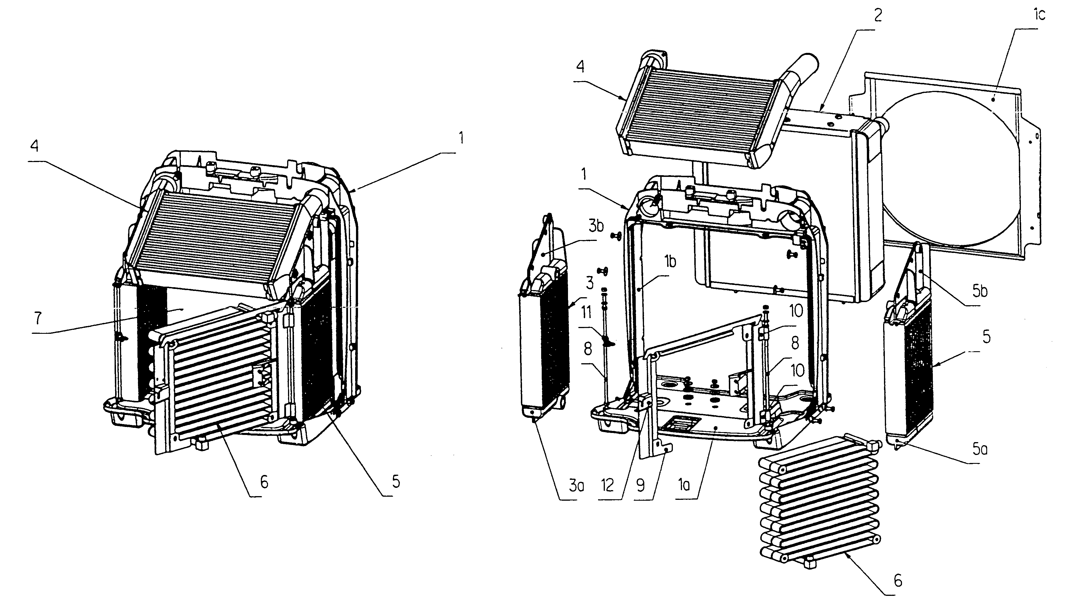
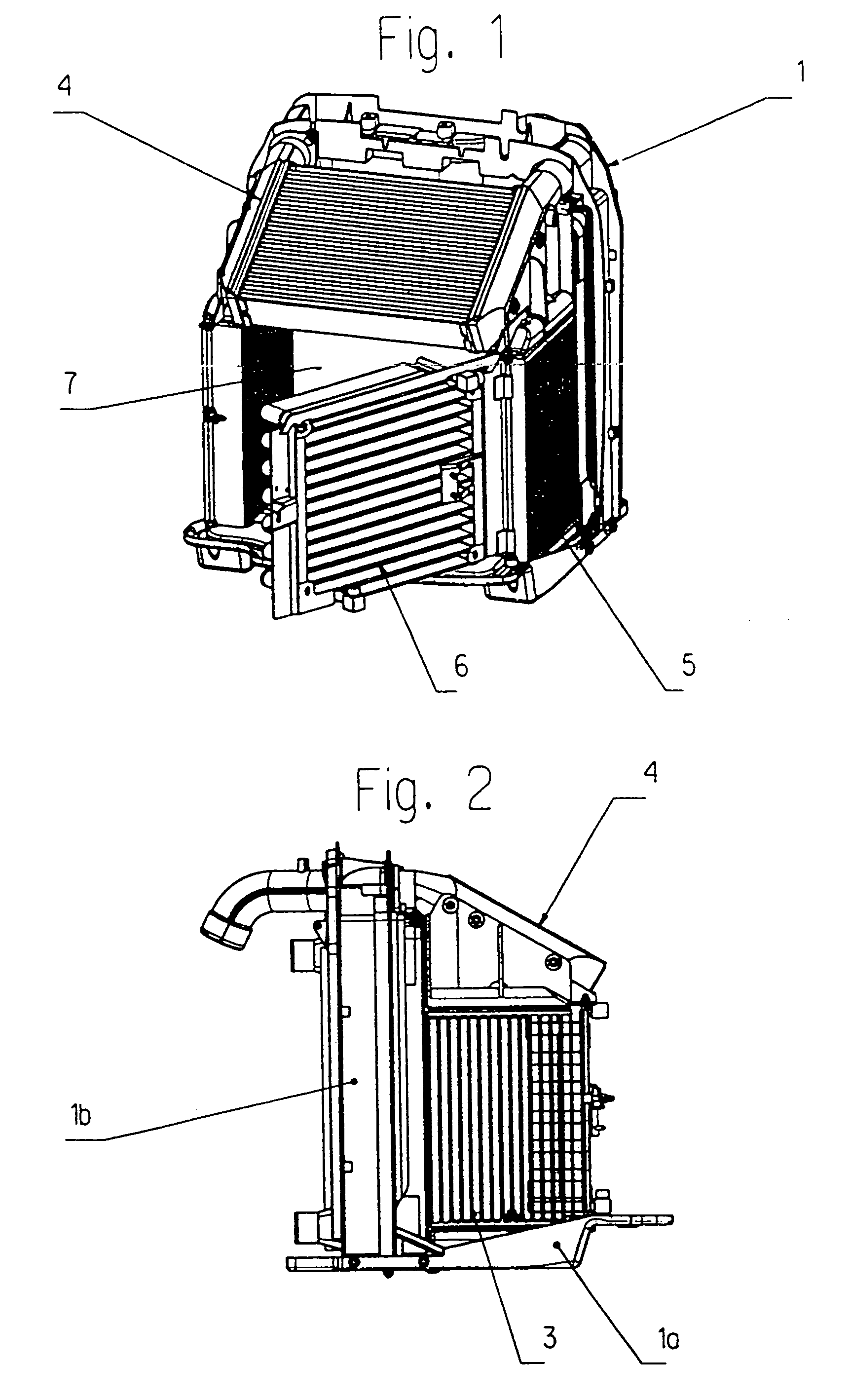
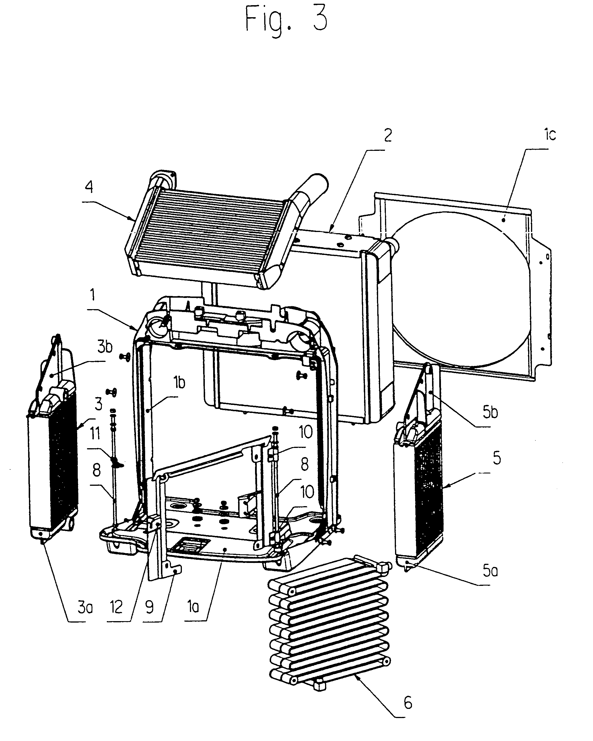
[0016]The cooling system illustrated in the drawings is designed to be provided as a pre-assembled unit which can be mounted and secured directly onto a vehicle frame, not illustrated, in front of a fan.

[0017]This unit has a radiator support 1, on which several radiators are arranged. These are a rear water radiator designated by reference 2, a gear oil radiator 3, a booster air radiator 4, a combined radiator 5 for hydraulic oil and fuel as well as a condenser 6 for the air-conditioning system. Depending on the vehicle and the application for which it will be used, radiators which are not required can be replaced by radiators for other media or by air permeable plates. This being the case, the replacement plates can be designed in such a way that they have the same resistance to through-flow as the radiator which they replace.

[0018]Being the radiator with the largest surface area in this embodiment, the water radiator 2 is mounted in the interior of a bracket 1b, which is secured a...


PUM


Abstract

An arrangement of radiators (2–6) for a utility vehicle, e.g., an agricultural tractor, comprising three or more cooling radiators which together define a chamber (7), optionally with some of the walls formed by perforated plates instead of radiator elements. One of the radiator elements may be pivotally mounted with respect to the others to provide access to the chamber. The arrangement of radiators may be mounted on a common support (1).

Description

BACKGROUND TO THE INVENTION[0001]The invention relates to an arrangement of three or more cooling radiators for a utility vehicle, such as an agricultural tractor.[0002]Powerful utility vehicles, such as agricultural tractors, for example, require a number of radiators in order to re-cool the working media, such as coolant water for the engine, transmission oil and hydraulic oil amongst others, as they become heated during use. These days, it is common practice to provide the requisite radiators in a parallel arrangement one after the other so that the coolant air flows through radiators. However, there are certain disadvantages to this layout. Arranging the radiators one after the other results in a high resistance to air flow which, apart from making it necessary to provide a disproportionately powerful fan, can also cause lead to an interruption in the flow, which results in the radiators becoming overheated. The lower temperature differential available to the radiators also make...

Claims


Application Information

Patent Timeline
Patent Type & Authority Patents(United States)
IPC IPC(8): B60K11/04F28D1/04F28F9/00
CPCB60K11/04F28D1/0426F28F9/002B60Y2200/221B60Y2200/41F28D2021/0084F28D2021/0087F28D2021/0089F28D2021/0094F28F2280/105F02B29/0431Y02T10/12
Inventor HEINLE, HANSHEROLD, MICHAELSPRENZEL, ALOISWAGNER, WALTER
Owner AGCO GMBH
Learn More