Supercharge Your Innovation With Domain-Expert AI Agents!

True RMS converter board

a converter board and converter board technology, applied in the direction of optical radiation measurement, receiver monitoring, instruments, etc., can solve the problems of increasing the test time for each component, requiring an inordinate amount of manpower and equipment to process the testing of the components quickly, and testing is often not repeatable, so as to achieve the effect of conserving resources

Inactive Publication Date: 2006-10-31
II VI DELAWARE INC
View PDF1 Cites 4 Cited by
  • Summary
  • Abstract
  • Description
  • Claims
  • Application Information

AI Technical Summary

Benefits of technology

Enables efficient and repeatable testing of optical components by separating and converting AC and DC signals to their RMS values, reducing resource consumption and test time while maintaining accuracy.

Problems solved by technology

Many of these tests have conventionally been performed using expensive high-frequency test equipment.
As such, these devices require excessive amounts of human interaction to perform the test result in and increase test times for each component.
When each and every component manufactured is tested, this requires an inordinate amount of manpower and equipment to process testing of the components quickly.
Additionally, testing is often not repeatable from part to part.

Method used


Image

  • True RMS converter board
  • True RMS converter board
  • True RMS converter board

Examples


Embodiment Construction

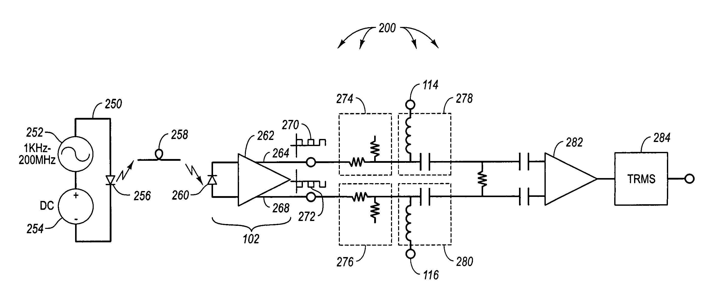
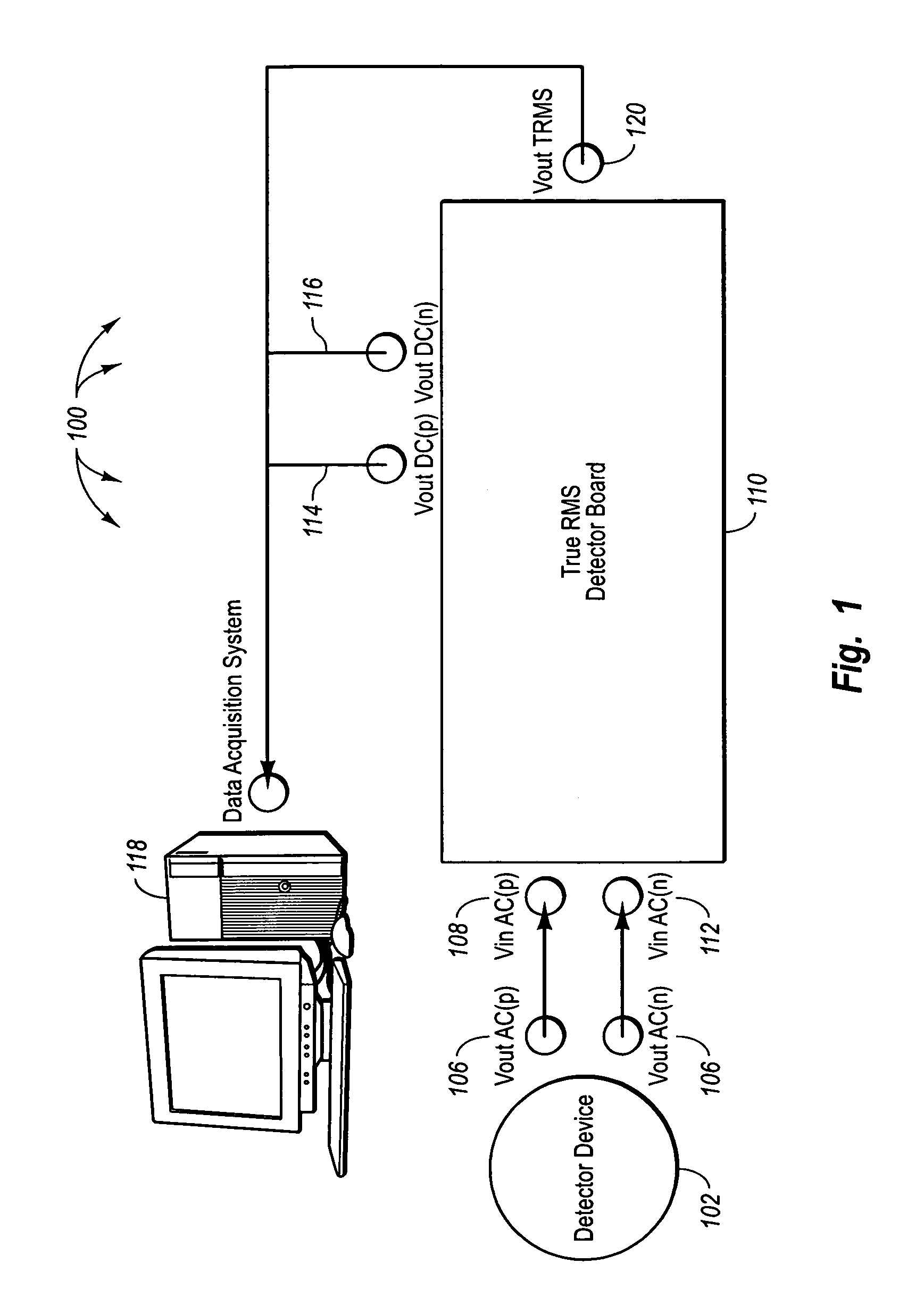
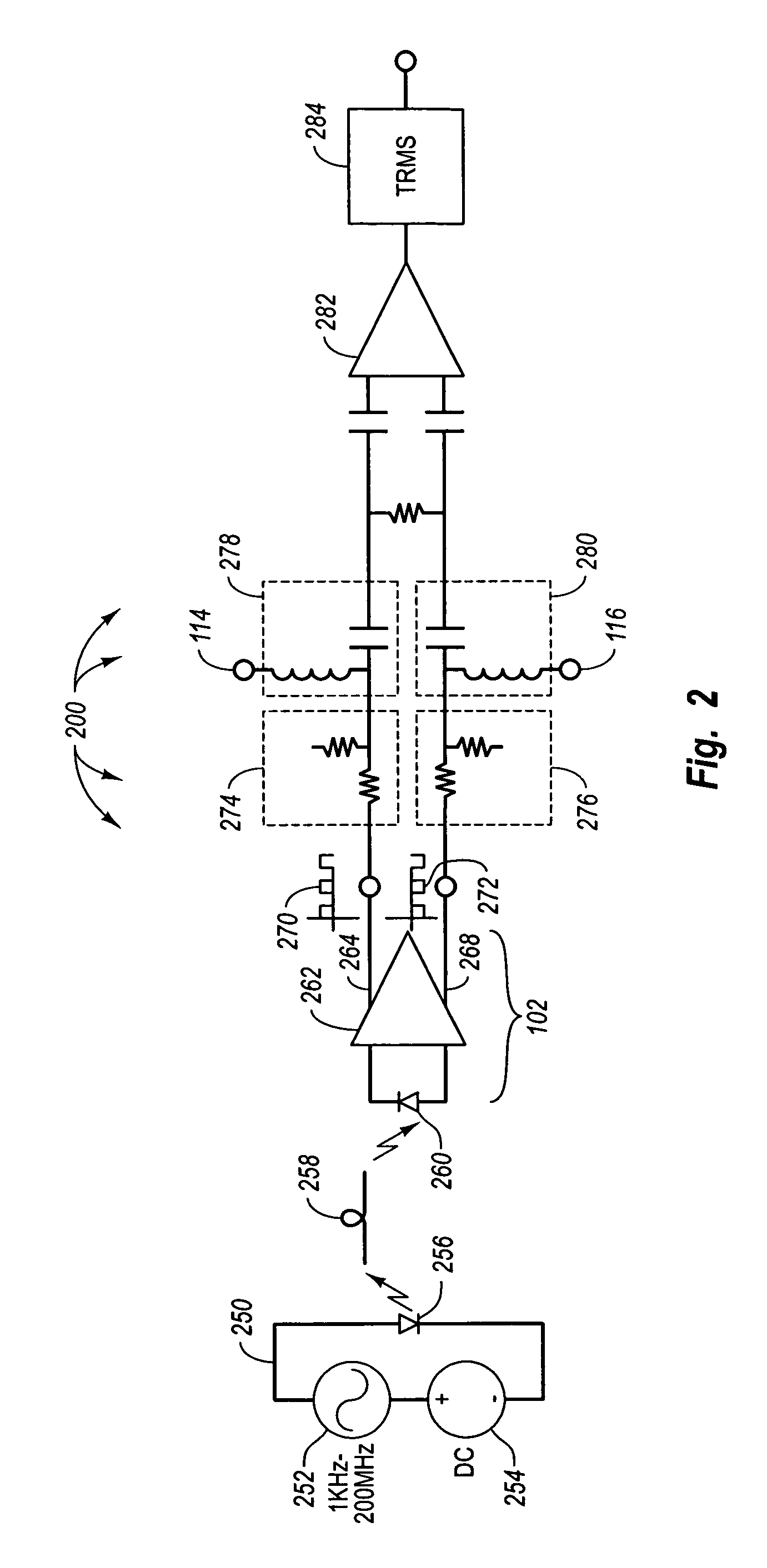
[0020]Referring now to FIG. 1, an embodiment of the invention is illustrated as a test apparatus 100 that provides for monitoring of AC and DC signals produced by a transmitter. The apparatus 100 shown in FIG. 1 may be used to test transmitter devices. In one example, the transmitter device may be a TOSA or a transmitter which includes a laser diode or light emitting diode (LED). The apparatus shown in FIG. 1 includes a detector device 102. The detector device 102 may be for example a detector that includes a photodiode coupled to a transimpedance amplifier with a differential output. The detector device 102 will be discussed in more detail with reference to FIG. 2 described herein. The detector device 102 outputs a positive output signal at a positive output signal terminal 104 and a negative output signal at a negative output terminal 106. The positive output signal is fed into a positive input port 108 of an RMS detector board 110. Similarly the negative output signal is input to...


PUM


Abstract

A true RMS conversion circuit. A test apparatus includes a transmitter source including AC and DC supplies. The transmitter source can connect to a transmitter. The test apparatus includes an optical receiver to receive optical signals from a transmitter coupled to the transmitter source. The optical receiver includes an amplifier with a differential output. The test apparatus also includes a matching networks connected to a high and low outputs. Also included in the test apparatus are filters connected to the matching networks. The filters are designed to separate AC and DC signals. An RMS conversion circuit is connected to the filters such that the RMS conversion circuit receives AC signals from the filters. The RMS conversion circuit converts the AC signals to a DC function of the RMS value of the AC signals. A data acquisition system is connected to the RMS conversion circuit to receive the function of the RMS value of the AC signals. The data acquisition system is connected to the filters to receive DC signals from the filters.

Description

CROSS-REFERENCE TO RELATED APPLICATIONS[0001]This application claims the benefit of U.S. Provisional Application No. 60 / 599,259, titled “True RMS Converter Board” filed Aug. 4, 2004, which is incorporated herein by reference.BACKGROUND OF THE INVENTION[0002]1. The Field of the Invention[0003]The invention generally relates to fiber-optic test equipment. More specifically, the invention relates to test equipment for testing optical transmitters and receivers used in fiber-optic communications.[0004]2. Description of the Related Art[0005]Fiber-optic networking can be used to communicate in modern high-speed networks. To transmit data on a fiber-optic network, the data must be converted from an electronic signal to an optical signal. This conversion may be done, for example, by using a transmitter or transmitting optical subassembly (TOSA). The transmitters and TOSAs often include light generating devices such as a laser or light emitting diode (LED). The light generating device is mod...

Claims


Application Information

Patent Timeline
Patent Type & Authority Patents(United States)
IPC IPC(8): G01R19/00G01G1/42
CPCH04B17/24
Inventor LALONDE, ANDRE
Owner II VI DELAWARE INC
Features
  • R&D
  • Intellectual Property
  • Life Sciences
  • Materials
  • Tech Scout
  • Unparalleled Data Quality
  • Higher Quality Content
  • 60% Fewer Hallucinations
Learn More