Piezoelectric vibration element and piezoelectric filter

a technology of piezoelectric filter and vibration element, which is applied in the direction of oscillation generator, generator/motor, device material selection, etc., to achieve the effect of stable characteristic and stable filter characteristi

Inactive Publication Date: 2006-10-31
PANASONIC CORP
View PDF9 Cites 12 Cited by
  • Summary
  • Abstract
  • Description
  • Claims
  • Application Information

AI Technical Summary

Benefits of technology

[0013]The present invention offers a piezoelectric oscillator using zinc oxide as a piezoelectric material. Unwanted resonance called inharmonic overtone is eliminated by optimizing ratio Le / H of driving electrode length Le to oscillator thickness H in the piezoelectric oscillator using thickness extension vibration or thickness shear vibration as main vibration.
[0014]Moreover, a ladder-type piezoelectric filter or multi-mode piezoelectric filter is manufactured by employing the piezoelectric oscillator of the present invention. These piezoelectric filters demonstrate stable filter characteristic without ripple in a passband because each oscillator features stable characteristic without unwanted resonance.

Problems solved by technology

However, in case of the piezoelectric oscillator, vibrations other than s_0, the main vibration, become unwanted resonance called inharmonic overtone.
However, for the piezoelectric oscillator using zinc oxide as a piezoelectric material, a designed value for electrode which does not generate unwanted resonance called inharmonic overtone is not yet identified.

Method used


Image

  • Piezoelectric vibration element and piezoelectric filter
  • Piezoelectric vibration element and piezoelectric filter
  • Piezoelectric vibration element and piezoelectric filter

Examples


first exemplary embodiment

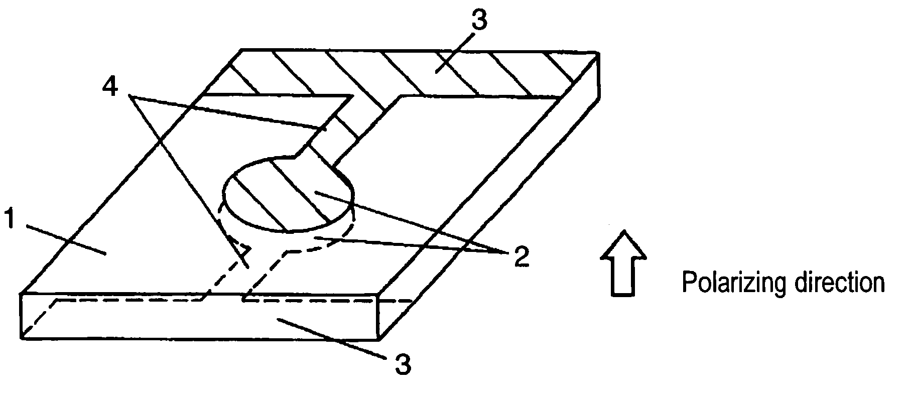
[0078]FIG. 11 is a piezoelectric oscillator which uses zinc oxide as a piezoelectric material, is polarized in a thickness direction of the piezoelectric plate, and uses thickness extension vibration as main vibration. This piezoelectric oscillator includes vibrating section 1, driving electrodes 2 disposed at positions facing each other on the top and bottom faces of vibrating section 1, lead electrode 3 and electrode 4 for external draw-out.

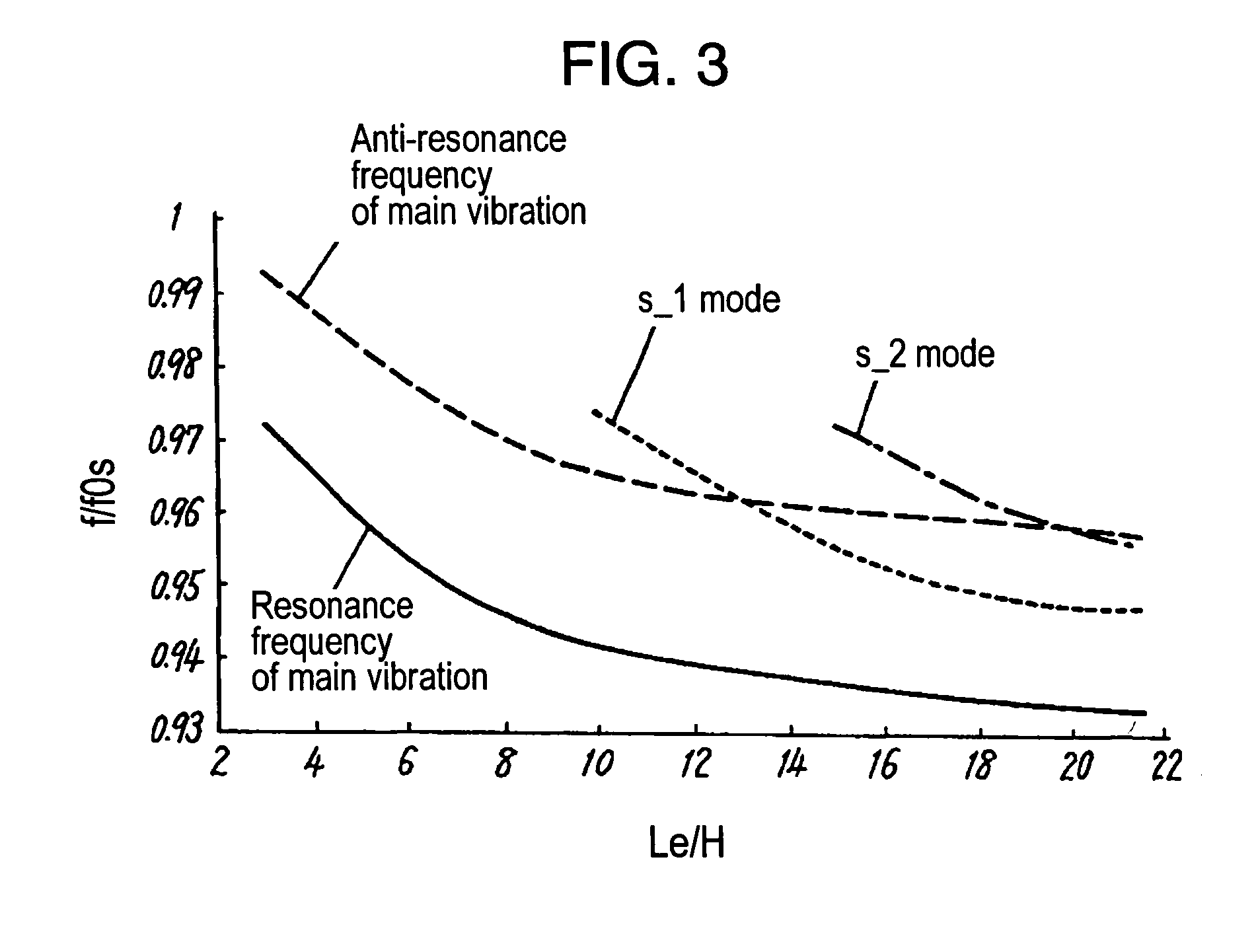
[0079]In the first exemplary embodiment, the resonance frequency is about 15 MHz so as to achieve oscillator thickness H of 200 μm. The driving electrode is square with 2 mm for each side. Accordingly, the ratio of the driving electrode length to oscillator thickness is 10. In other words, the ratio falls within the range of 4 to 13, achieving stable characteristic without unwanted resonance between the resonance frequency and anti-resonance frequency of the main vibration.

second exemplary embodiment

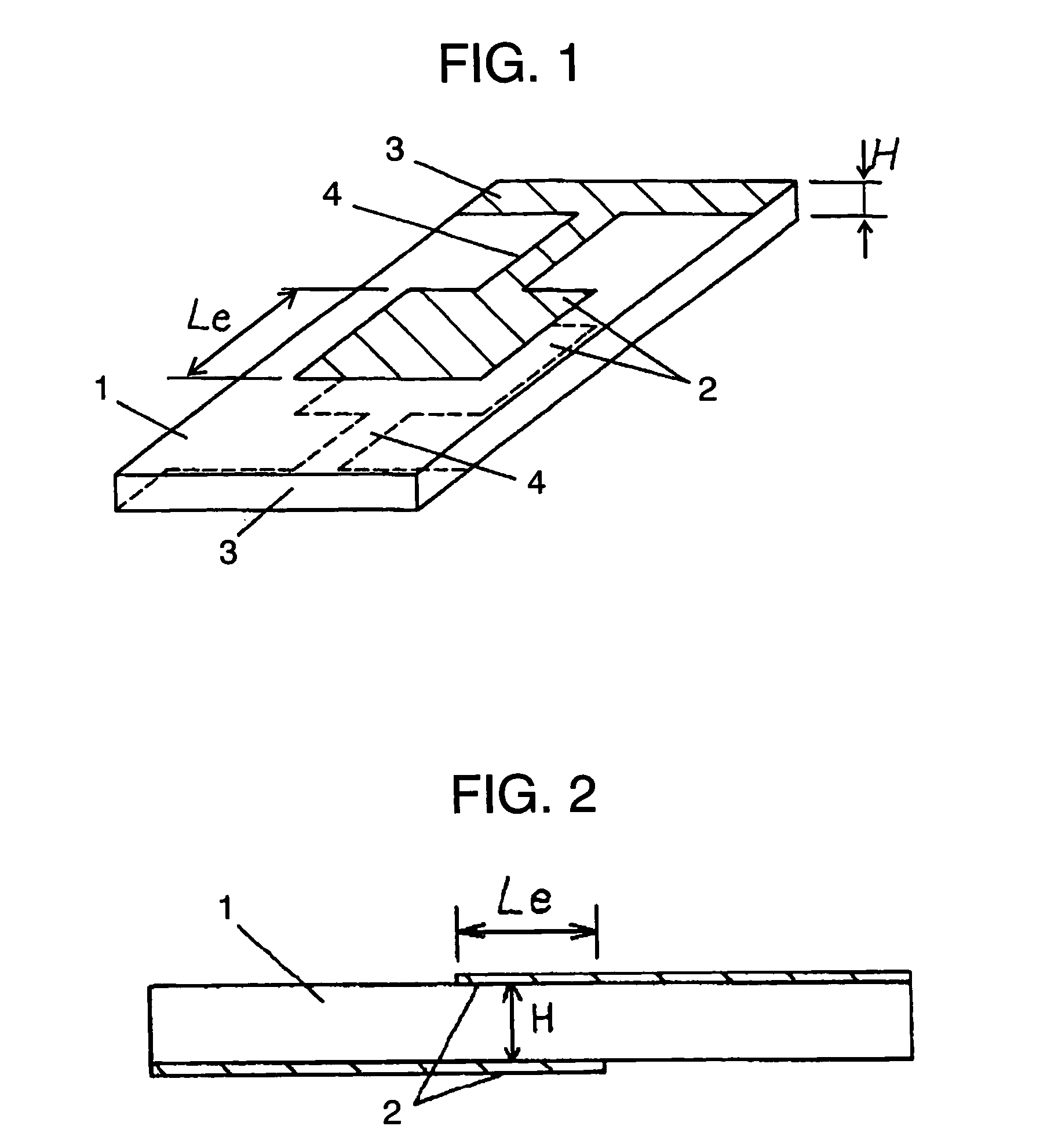
[0080]FIG. 12 is a piezoelectric oscillator which uses zinc oxide as a piezoelectric material, is polarized in a thickness direction of the piezoelectric plate, and uses thickness extension vibration as main vibration. This piezoelectric oscillator includes vibrating 1, driving electrodes 2 disposed at positions facing each other on the top and bottom faces of vibrating section 1, lead electrode 3, and electrode 4 for external draw-out.

[0081]The resonance frequency is about 1.5 GHz because oscillator thickness H is 2 μm. The driving electrode is a round electrode with 60 μm diameter. Its high operating frequency keeps the gain difference between the resonance and anti-resonance of inharmonic overtone small, achieving preferable characteristic without detrimental effect of unwanted resonance between the resonance frequency and anti-resonance frequency of the main vibration. In addition, low impedance and high Q for resonance of the main vibration are achievable.

third exemplary embodiment

[0082]FIG. 13 is a piezoelectric oscillator which uses zinc oxide as a piezoelectric material, is polarized in a length direction of the piezoelectric plate, and uses thickness shear vibration as main vibration. This piezoelectric oscillator includes vibrating section 1, driving electrodes 2 disposed at positions facing each other on the top and bottom faces of vibrating section 1, lead electrode 3, and electrode 4 for external draw-out.

[0083]The resonance frequency is about 7 MHz because oscillator thickness H is 200 μm. Driving electrode length is 3 mm. This makes the ratio of the driving electrode length to oscillator thickness within the range of 7 to 23, achieving stable characteristic without unwanted resonance between the resonance frequency and anti-resonance frequency of the main vibration.


PUM


Abstract

A piezoelectric oscillator using zinc oxide as a piezoelectric plate which eliminates unwanted resonance called inharmonic overtone by optimizing ratio Le / H of driving electrode length Le to oscillator thickness H. Ratio Le / H is set between 4 and 100 in the piezoelectric oscillator polarized in a thickness direction of a piezoelectric plate and using thickness extension vibration as main vibration or the piezoelectric oscillator polarized in a length direction of the piezoelectric plate and using thickness shear vibration as main vibration. This achieves stable characteristic because no unwanted resonance exists between the resonance frequency and anti-resonance frequency of the main vibration.

Description

[0001]THIS APPLICATION IS A U.S. NATIONAL PHASE APPLICATION OF PCT INTERNATIONAL APPLICATION PCT / JP02 / 03176.TECHNICAL FIELD[0002]The present invention relates to piezoelectric oscillators and piezoelectric filters using zinc oxide as a piezoelectric material.Background Art[0003]Piezoelectric oscillators using a bulk wave traveling through a solid includes piezoelectric oscillators employed as a clock source for diversifying electronic apparatuses and piezoelectric filters for extracting frequencies in communications apparatuses. Recently, operating frequency bands of these piezoelectric oscillators are becoming increasingly higher. In these piezoelectric oscillators, thickness vibration such as thickness shear vibration and thickness extension vibration is used as main vibration. In particular, the energy trapping phenomenon which facilitates the suppression of unwanted vibration and retention of the oscillator is often applied. Energy trapping is a phenomenon that vibration energy ...

Claims


Application Information

Patent Timeline
Patent Type & Authority Patents(United States)
IPC IPC(8): H03B5/32H01L41/09H01L41/18H03H9/17H03H9/56H03H9/58
CPCH03H9/132H03H9/177H03H9/562H03H9/581
Inventor SASAKI, YUKINORI
Owner PANASONIC CORP
Why Eureka
Try Eureka