Stripline Filter and Manufacturing Method Thereof

a technology of stripline filter and manufacturing method, which is applied in the direction of superimposed coating process, liquid/solution decomposition chemical coating, waveguide, etc., can solve the problems of poor connection of electrodes, limited element size reduction, and low efficiency etc., to achieve stable filter characteristics, high efficiency percentage, and extended line length of l-shaped resonant lines

Inactive Publication Date: 2010-10-21
MURATA MFG CO LTD
View PDF4 Cites 3 Cited by
  • Summary
  • Abstract
  • Description
  • Claims
  • Application Information

AI Technical Summary

Benefits of technology

[0023]According to the invention, the line length of the L-shaped resonant line can be extended and the length by which the resonant line faces the adjacent resonant line can also be extended. Thus, even when the element size of the stripline filter is small, a great resonator length and facing length can be obtained, and optional filter characteristics can be achieved. In addition, the connectivity with the side surface line can be secured by the wide connection electrode part, and the width of the connection portion does not change even when the side surface line is deviated. Further, since the edge of the first line part is spaced from the edge of the dielectric substrate, the electrode size of the first line part does not change even when the cutting position of dicing varies. Therefore, a high efficiency percentage can be achieved with optional stable filter characteristics, and the element size can be reduced.

Problems solved by technology

Thus, the element size expanded by the lengths of the wide electrode parts needs to be secured, and hence the reduction of the element size is limited.
The accuracy for forming the electrodes on the side surfaces is likely to deteriorate when compared to that for forming electrodes on a top surface or a bottom surface of a dielectric substrate.
Due to this change, a poor connection of the electrodes occurs or filter characteristics vary.
Thus, there is a possibility that the efficiency percentage of products will be reduced.
In addition, burring or peeling may occur at the electrode due to dicing.
Due to this as well, there is a possibility that the filter characteristics will vary and the efficiency percentage of products will be reduced.

Method used


Image

  • Stripline Filter and Manufacturing Method Thereof
  • Stripline Filter and Manufacturing Method Thereof
  • Stripline Filter and Manufacturing Method Thereof

Examples


Embodiment Construction

[0047]The following will describe an example of a configuration of a stripline filter according to an embodiment of the invention.

[0048]The stripline filter shown herein is a band-pass filter. The filter is used for UWB (ultra wide band) communication in a high frequency band equal to or higher than 4 GHz.

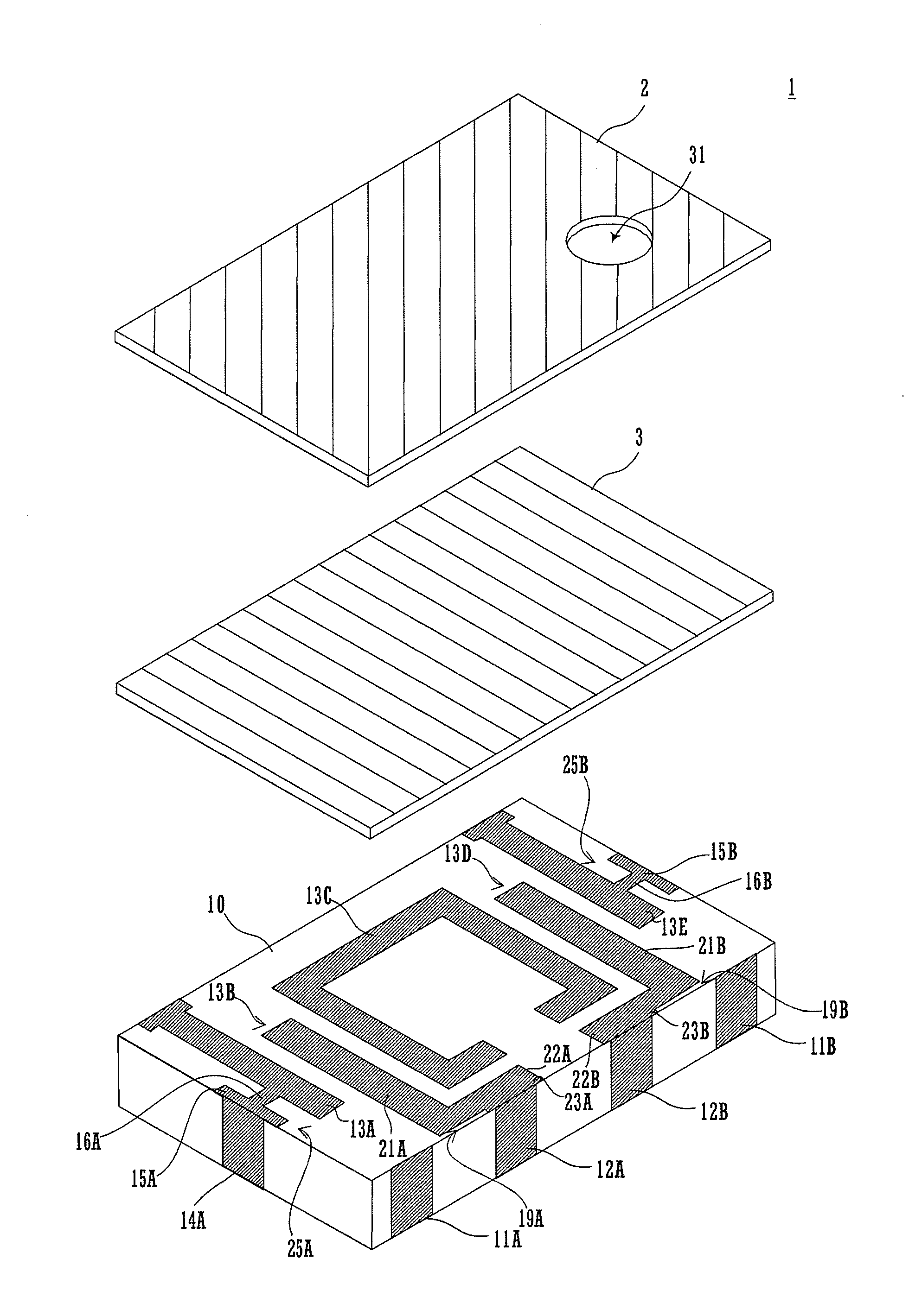
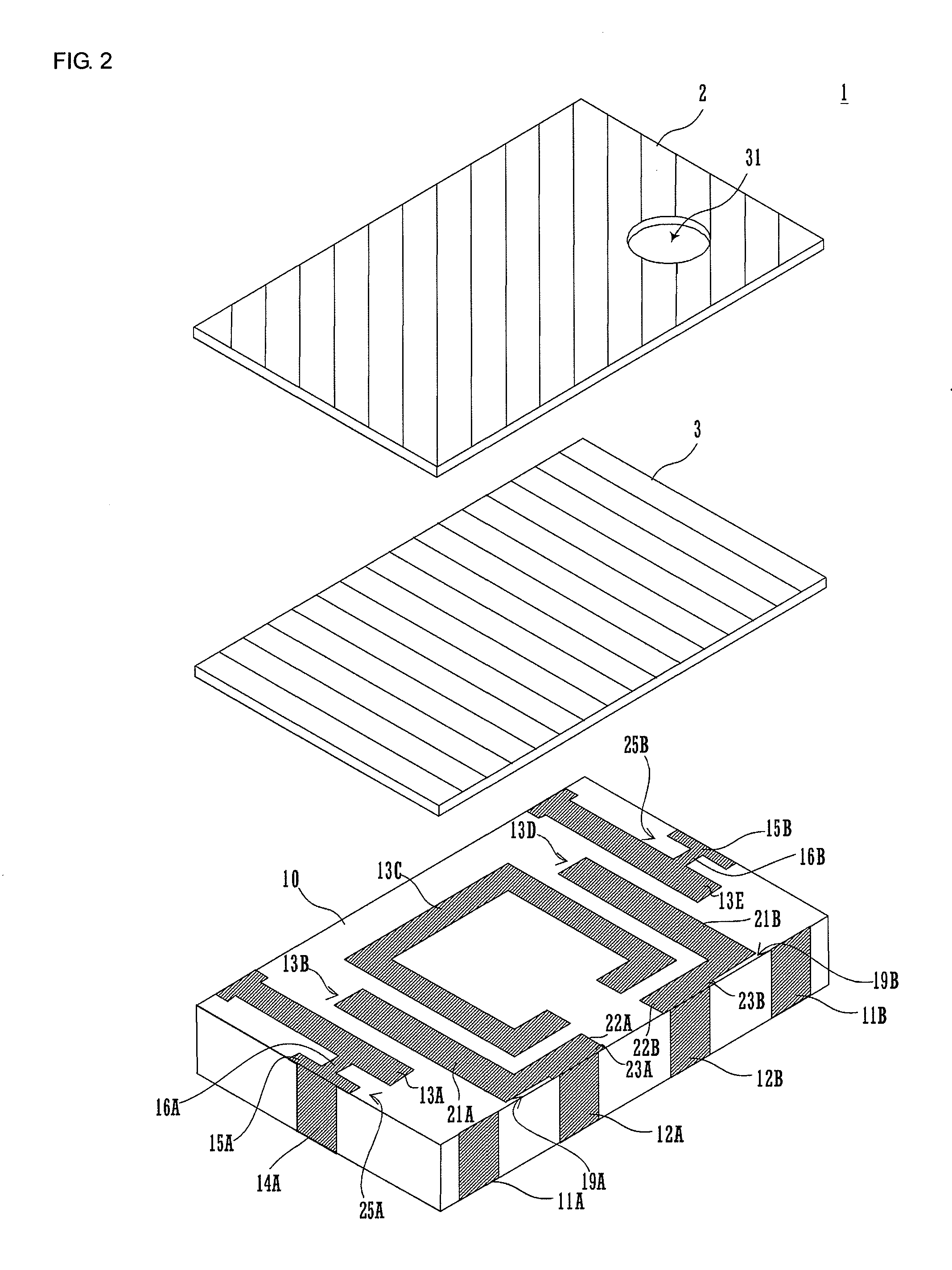
[0049]FIG. 2 is an exploded perspective view of the stripline filter on its top surface side. FIG. 3 is a perspective view of the stripline filter on its bottom surface.

[0050]The stripline filter 1 includes a dielectric substrate 10 and glass layers 2 and 3. Here, each of the glass layers 2 and 3 has a thickness of about 15 μm. The glass layers 2 and 3 are laminated on a top surface of the dielectric substrate 10, and contribute to mechanical protection and improvement of the environmental resistance, of the stripline filter 1. The glass layer 2 is laminated on the glass layer 3. Thus, a hole 31 can be formed as a marker in the glass layer 2, whereby the orientation of the striplin...


PUM

PropertyMeasurementUnit
frequencyaaaaaaaaaa
thicknessaaaaaaaaaa
relative dielectric constantaaaaaaaaaa

Abstract

The element size of a stripline filter that achieves a high efficiency percentage with optional stable filter characteristics, is reduced. A stripline filter includes substantially L-shaped top surface resonant lines. The top surface resonant lines include connection electrode parts, first line parts, and second line parts. The connection electrode parts are formed so as to have a width greater than line widths of side surface resonant lines. Each line part faces an edge of a corner portion of a central top surface resonant line at an interval. An edge of each first line part on an edge side of a dielectric substrate, other than a connection portion with the connection electrode part, faces an edge of the dielectric substrate at an interval.

Description

CROSS REFERENCE TO RELATED APPLICATIONS[0001]The present application is a continuation of International Application No. PCT / JP2008 / 072032, filed Dec. 4, 2008, which claims priority to Japanese Patent Application No. JP2007-326842, filed Dec. 19, 2007, the entire contents of each of these applications being incorporated herein by reference in their entirety.FIELD OF THE INVENTION[0002]The present invention relates to a stripline filter in which striplines are provided on a dielectric substrate, and a manufacturing method thereof.BACKGROUND OF THE INVENTION[0003]A stripline filter in which a stripline-type resonator is provided on a dielectric substrate, is used in various fields (e.g., see Patent Document 1).[0004]Here, a configuration of an existing stripline filter will be described. FIG. 1 is a top perspective view of the stripline filter.[0005]In the stripline filter 101 resonant lines 113A and 113B are formed on a top surface of a dielectric substrate 110. The resonant line 113A...

Claims


Application Information

Patent Timeline
Patent Type & Authority Applications(United States)
IPC IPC(8): H01P1/203B05D5/12
CPCH01P1/20354H01P11/007H01P1/20381
Inventor HONDA, NOBUYOSHITSUJIGUCHI, TATSUYATAKEI, YASUNORI
Owner MURATA MFG CO LTD
Why Eureka
Try Eureka