
System and method for feature-based light field morphing and texture transfer

a technology of light field and feature, applied in the field of three-dimensional morphing objects, can solve the problems of difficult to recover detailed surface geometry from images, require extensive user input or interaction, and are very computationally expensive, and achieve the effect of easy work with objects

Inactive Publication Date: 2006-10-31
MICROSOFT TECH LICENSING LLC
View PDF4 Cites 18 Cited by
  • Summary
  • Abstract
  • Description
  • Claims
  • Application Information

AI Technical Summary

Benefits of technology

[0010]Light field morphing, as described herein, provides a general framework for image-based three-dimensional (3D) morphing and texture transfer. In general, a “light field morpher,” as described herein, provides a computationally efficient system and method for morphing of 3D objects. Note that this morphing also includes the capability to transfer textures from one 3D object to another. The light field morpher accomplishes the morphing and texture transfer of 3D objects based on the morphing of “light fields,” or “lumigraphs,” associated with source and target 3D objects having either or both Lambertian, or non-Lambertian surfaces, without the need for object modeling, or otherwise recovering detailed object geometry. Consequently, one clear advantage of the light field morpher over conventional morphing schemes is the ability to easily work with objects that are difficult to model with traditional techniques. For example, because the light field morpher is capable of handling both Lambertian and non-Lambertian surfaces, light field morphing is applicable to objects having complex surface properties such as fur, subsurface scattering, and hypertextures.
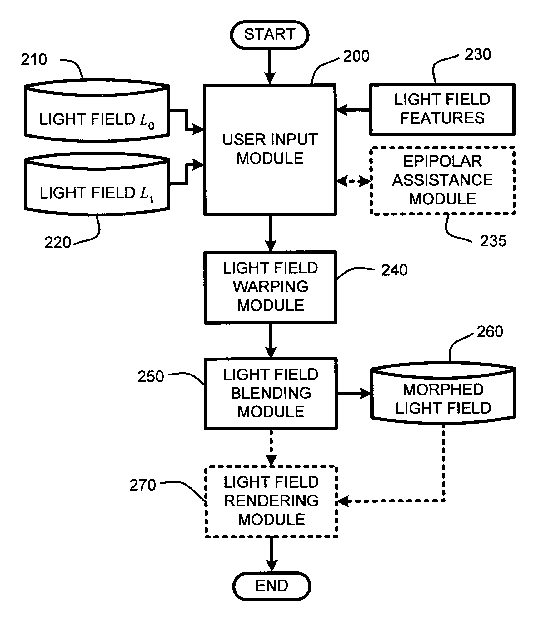
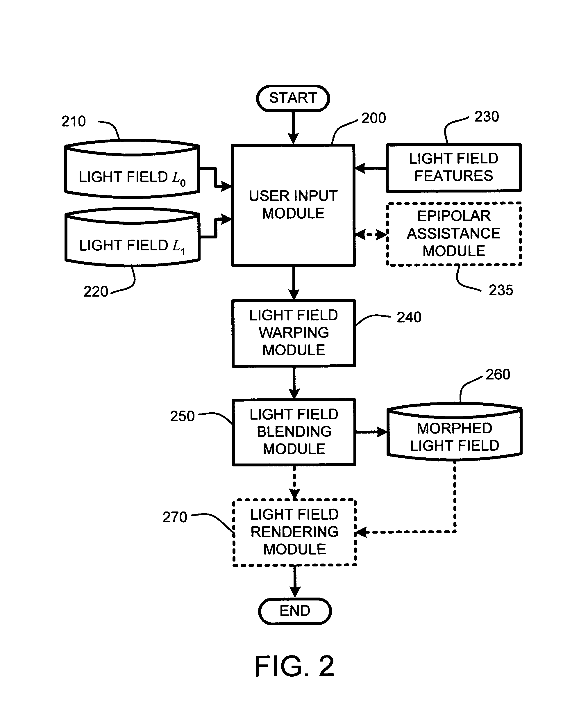
[0013]In a related embodiment, the user is automatically assisted in the specification of corresponding feature points by an automatic epipolar geometry-based recommendation system. Specifically, after the user specifies a feature point in a first light field view, an epipolar line is automatically displayed in a second light field view. The corresponding feature point in the second light field view is then simply selected from along the length of this epipolar line. Consequently, the use of the epipolar-geometry assisted point selection serves to reduce the time needed for manual selection of corresponding points, while increasing the accuracy of point correspondence.
[0019]In general, light field warping is accomplished by first computing feature elements and background edges for each warped light field by interpolating from the feature elements specified for the two input light fields, e.g., the source and target light fields. This interpolation is performed for feature points, feature lines, feature polygons, and background edges. While any desired interpolation method may be used, in a tested embodiment, simple linear interpolation was found to produce good results.
[0023]Note that for a given view of an object represented by a warped light field, “holes” are created by object shape changes when a hidden surface patch in the source light field becomes visible in the target light field. Such holes may be arbitrarily large. However, the holes are automatically filled during ray-space warping by approximating any occluded rays using a “nearest visible ray” for each feature polygon of the associated global visibility map. Further, this ray-space warping produces accurate results under a Lambertian surface assumption, while for non-Lambertian or specular surfaces, ray-space warping minimizes rendering errors by using the nearest visible rays based on the light field rays associated with each feature polygon of the global visibility map to assign pixel colors. In general, identification of the “nearest visible ray” is accomplished by searching each view plane of the model represented by the corresponding light field to identify a visible nearest neighbor. It should be noted that this search will never fail because each feature polygon will always be fully visible in at least one view plane.
[0024]Once the warped light fields have been computed, they are blended to produce a morphed light field of the object which represents the essential features of both the source and target objects. In one embodiment, a simple interpolation between each of the warped light fields is used to blend the warped light fields to create a composite light field representing the morph. In further embodiments, any of a number of conventional blending, feathering, and deghosting techniques is used in combining the two warped light fields to improve the image quality of the composite light field representing the morph. This morph can then be displayed using conventional light field rendering techniques to render the blended light field representing the morph.
[0025]Finally, in another embodiment, the transfer of 3D textures from one 3D object or model to another is accomplished as a straightforward application of light field morphing. In particular, in implementing such plenoptic texture transfer, after establishing ray correspondence between the source and target light fields as described above, the colors of source light field rays are simply assigned to the corresponding target light field rays. The result is a computationally efficient and realistic texture transfer from the source model to the target model.

Problems solved by technology

Unfortunately, where the geometry is unknown or difficult to model, such conventional 3D morphing schemes fail to create realistic morphs.
However, such methods either require extensive user input or interaction, or are very computationally expensive, or both.
Visibility issues can be resolved with the recovered geometry, but there are problems, including a Lambertian surface assumption needed for voxel carving, and fundamental difficulties associated with recovering detailed surface geometry from images.
Consequently, the use of Lambertian surfaces fails to consider specular components to the reflected spectrum that exists on real, or non-Lambertian, surfaces.
Such real, or non-Lambertian, surfaces typically exhibit specular characteristics that are not adequately modeled by this plenoptic editing scheme.

Method used


Image

  • System and method for feature-based light field morphing and texture transfer
  • System and method for feature-based light field morphing and texture transfer
  • System and method for feature-based light field morphing and texture transfer

Examples


Embodiment Construction

[0044]In the following description of the preferred embodiments of the light field morpher, reference is made to the accompanying drawings, which form a part hereof, and in which is shown by way of illustration specific embodiments in which the invention may be practiced. It is understood that other embodiments may be utilized and structural changes may be made without departing from the scope of the present invention.

1.0 Exemplary Operating Environment:

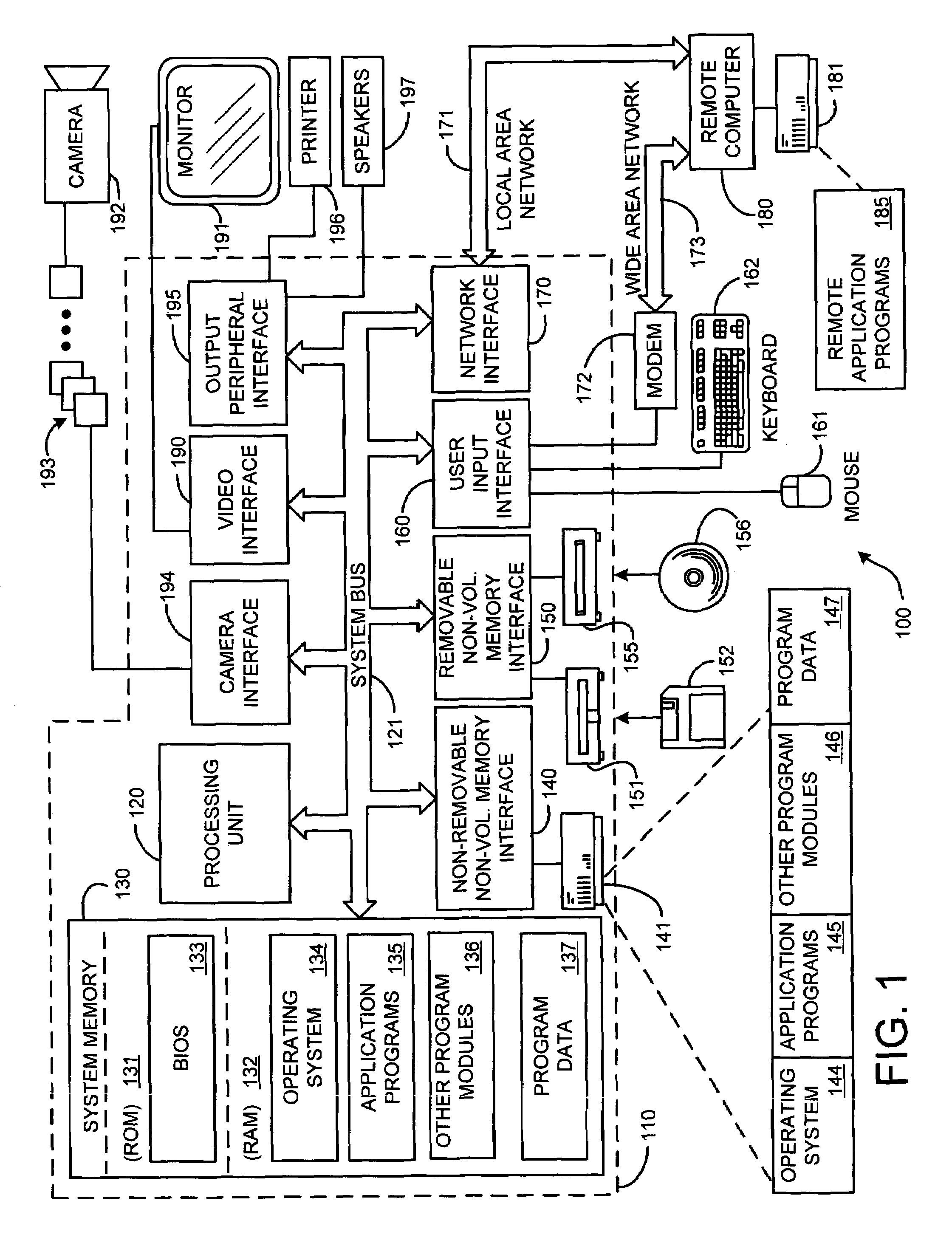
[0045]FIG. 1 illustrates an example of a suitable computing system environment 100 on which the invention may be implemented. The computing system environment 100 is only one example of a suitable computing environment and is not intended to suggest any limitation as to the scope of use or functionality of the invention. Neither should the computing environment 100 be interpreted as having any dependency or requirement relating to any one or combination of components illustrated in the exemplary operating environment 100.

[0046]The in...


PUM


Abstract

A “light field morpher,” as described herein, provides a computationally efficient system and method for image-based three-dimensional (3D) morphing and texture transfer of 3D objects by morphing “light fields” or “lumigraphs,” associated with source and target 3D objects. The light field morpher is applicable to morphing of objects having either or both Lambertian, or non-Lambertian surfaces, including surfaces having complex properties such as fur, subsurface scattering, and hypertextures, without the need for object modeling, or otherwise recovering detailed object geometry. Light field morphing begins by first specifying corresponding 2D and 3D feature elements, such as, “feature lines,”“feature polygons,” and “background edges,” in the input light fields representing the source and target light fields. Once the feature elements have been specified, “ray-space warping” of both light fields then warps those light fields to produce feature alignment. These warped light fields are then blended to produce a light field morph.

Description

BACKGROUND[0001]1. Technical Field[0002]The invention is related to morphing three-dimensional objects represented by light fields, and in particular, to a system and method for image-based three-dimensional morphing and texture transfer based on a correspondence between rays of source and target light fields.[0003]2. Related Art[0004]Metamorphosis, or morphing, is a popular technique for creating visual effects. In general, image morphing is the construction of an image sequence depicting a gradual transition between two images. Thus, when used effectively, morphing can produce a compelling illusion that an object is smoothly transforming from one object into another. Morphing two-dimensional (2D) images simply morphs the images themselves. However, when morphing images represented by three-dimensional (3D) models, intermediate 3D models; i.e., “morphs” are typically generated directly from the given models rather than simply morphing the images themselves. These morphs are then re...

Claims


Application Information

Patent Timeline
IPC IPC(8): G06T15/00G06T3/00G06T15/20G06T15/60
CPCG06T15/205
Inventor ZHANG, ZHUNPINGWANG, LIFENGGUO, BAININGSHUM, HEUNG-YEUNG
Owner MICROSOFT TECH LICENSING LLC
Learn More