Helical-ribbon mixer

a technology of helicalribbon and mixer, which is applied in the direction of mixers, mixers with rotary stirring, mixers, etc., to achieve good cross-intermixing, reduce edge friction and crush the material

Active Publication Date: 2006-11-07
BACKHAUS MARTIN
View PDF8 Cites 20 Cited by
  • Summary
  • Abstract
  • Description
  • Claims
  • Application Information

AI Technical Summary

Benefits of technology

[0020]The slope of the helical ribbon, in this additional embodiment, is oriented toward the center of the mixing vessel. This results in a friction of the material that is located on the helical ribbon toward the adjoining downward flowing material so that the circular forward force of the helix creates a lifting force of the material on the helix. However, a portion of the material to be mixed is also pushed off laterally into the centrical downward flow, so that smaller partial flows occur in the entire circulation, which produce an added local intermixing.
[0021]These partial flows are further enhanced when the width of the screw helix increases or decreases with an increasing height, so that the partial flows are formed cascade-like offset in the radial direction, i.e., a good cross-intermixing is attained.
[0022]The helical ribbon is advantageously provided at its lower edge facing the center of the vessel with a steeply downward pointing screw web, which prevents the flow from entering underneath the helical ribbon.
[0023]It is furthermore advantageous to design the helical ribbon on its side face closest to the wall downwardly divergent from the wall, which further reduces the edge friction and a crushing of the material to be mixed.
[0024]The radially sloped design of the screw helix has proven useful with wall-heated mixers as the time of direct contact of the material to be mixed with the wall is only short in each case until it is replaced by the following material, which results in an acceleration of the heat distribution toward the center of the mixer as compared to previously known mixers and is more homogenous, and there also is no overheating and caking of the material to the wall. The inwardly sloped shape of the helical ribbon has proven useful for preparing a paste and kneading doughy material, with the direction of operation of the helical ribbon drive being changed during the operating phases.

Problems solved by technology

One problem associated with these mixers is emptying them as residue-free as possible, for which purpose the agitator arm that holds the helical ribbon at its lower end is designed with a special shape, so that it clears the vessel bottom while placing little stress on the material to be mixed.

Method used


Image

  • Helical-ribbon mixer
  • Helical-ribbon mixer
  • Helical-ribbon mixer

Examples


Embodiment Construction

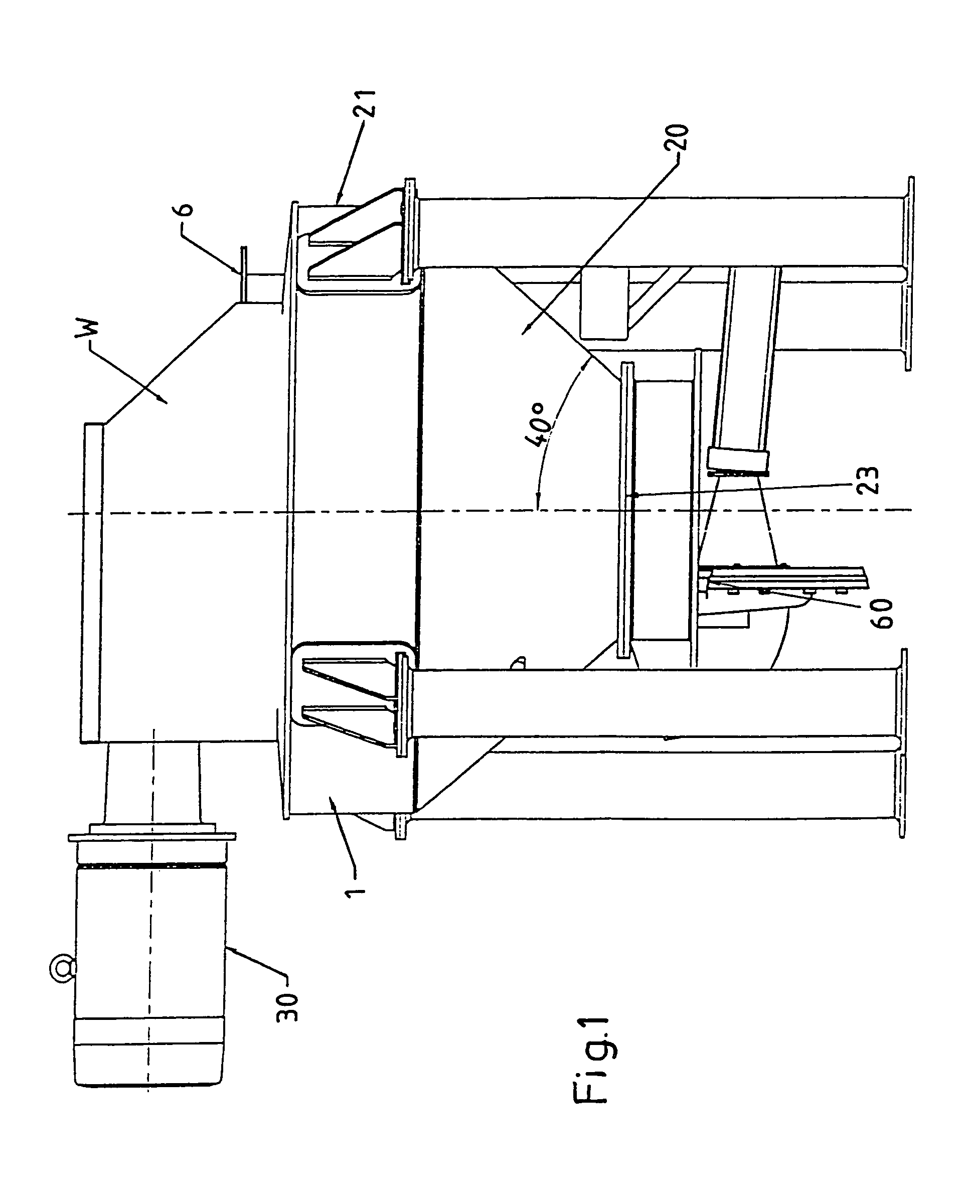
[0040]FIG. 1 shows a side view of a mixing vessel 1 having a filler neck 6 on top and a controllably closeable outlet 60 in the bottom region 23. The mixing vessel 1 incorporates mixing vessel sections 20, 21, 22, a cone section 20 of which, which diverges under approximately 80°, transitions into a cylindrical section 21 on top. On a lid, an agitator drive 30 is disposed with a motor and an angle drive W, which drives the agitator shaft, which is located centrically in the mixing vessel 1.

[0041]FIG. 2 clarifies, in the top view, the rotation-symmetrical design of the mixer and placement of the drive 30 with the gearing W and filler neck 6.

[0042]FIGS. 3 and 4 show a side view and FIG. 5 shows a top view of the mixer, which consists of a vertical agitator shaft 3 with agitator arms 5 and two helical ribbons 4A, 4B, which are located radially outside with a small lateral clearance S to the mixing vessel wall 2, of which only the inner contour is shown in the axial section. From the ap...


PUM


Abstract

A helical-ribbon mixer having a rotation-symmetrical inner mixing vessel wall (2), a motor-driven central agitator axis (3) therein, on which, on lateral agitator arms (5), at least one helical ribbon (4) is held close to the vessel wall downwardly sloping with a circular slope (SZ) in a direction of rotation (D), wherein the helical ribbon (4), vectorially combined circularly and radially, has a helical ribbon angle of slope (SN) relative to the horizontal that is greater than a gliding angle (G) on the helical ribbon (4) of a material (M) to be mixed.

Description

BACKGROUND OF THE INVENTION[0001]1. Technical Field of the Invention[0002]The present invention is concerned with a helical-ribbon mixer having a rotation-symmetrical inner mixing vessel wall, a motor-driven central agitator axis therein, on which, on lateral agitator arms, at least one helical ribbon is held close to the vessel wall, downwardly sloping with a circular slope in a direction of rotation.[0003]2. Prior Art[0004]A helical-ribbon mixer of this type is known from DE 195 47 220 C2. The helical ribbon serves to convey the material to be mixed in an upward flow near the wall, whereupon it flows back in a downflow near the axis and intermixes in the process. One problem associated with these mixers is emptying them as residue-free as possible, for which purpose the agitator arm that holds the helical ribbon at its lower end is designed with a special shape, so that it clears the vessel bottom while placing little stress on the material to be mixed. The helical ribbon is orien...

Claims


Application Information

Patent Timeline
Patent Type & Authority Patents(United States)
IPC IPC(8): B01F9/16B01F29/85A21C1/02
CPCA21C1/02B01F7/18B01F7/24B01F7/00275B01F7/00433B01F2215/0422B01F27/1123B01F27/1145B01F27/92B01F27/90
Inventor BACKHAUS, MARTIN
Owner BACKHAUS MARTIN
Why Eureka
Try Eureka