Collimator for high-energy radiation and program for controlling said collimator

a collimator and radiation technology, applied in the field of collimators for high-energy radiation and the control of collimators, can solve the problems of reducing the overall structure of the device, affecting the accuracy of the radiation, and reducing the scanning speed, so as to prevent leakage radiation, reduce weight, and the effect of the same outer contour

Inactive Publication Date: 2006-11-07
DEUTES KREBSFORSCHUNGSZENT STIFTUNG DES OFFENTLICHEN RECHTS
View PDF14 Cites 25 Cited by
  • Summary
  • Abstract
  • Description
  • Claims
  • Application Information

AI Technical Summary

Benefits of technology

[0008]It is therefore the underlying purpose of the invention to generate the contours of the objects to be treated with less expense but with more accuracy and in particular with an exact definition of the radiation fields.
[0026]The control unit is preferably a computer running a corresponding program. This facilitates changes to the working mode by changing the software. To be able to verify all adjustments made, the collimator advantageously comprises position detecting means for the actuating motions. Since the control unit is preferably designed such that the scanning process is carried out in accordance with a predetermined treatment plan, the position detecting means offer verification and optional correction of the adjustments.

Problems solved by technology

If the collimator is formed as simple opening, the overall structure of the device is still complicated, in particular in the embodiment variant of FIG. 3, wherein the collimator opening must be moved synchronously with the scanned beam.
This collimator is particularly disadvantageous in that the accuracy for defining the edges of the radiation fields depends on the size of the spot to be irradiated, which is formed by means of the collimator opening determined for this collimator.
Large radiation spots associated with large collimator openings increase the scanning speed but produce more inaccuracies.
Vice versa, small radiation spots result in slow scanning but lead to a more exact reproduction of the radiation field borders.

Method used


Image

  • Collimator for high-energy radiation and program for controlling said collimator
  • Collimator for high-energy radiation and program for controlling said collimator
  • Collimator for high-energy radiation and program for controlling said collimator

Examples


Embodiment Construction

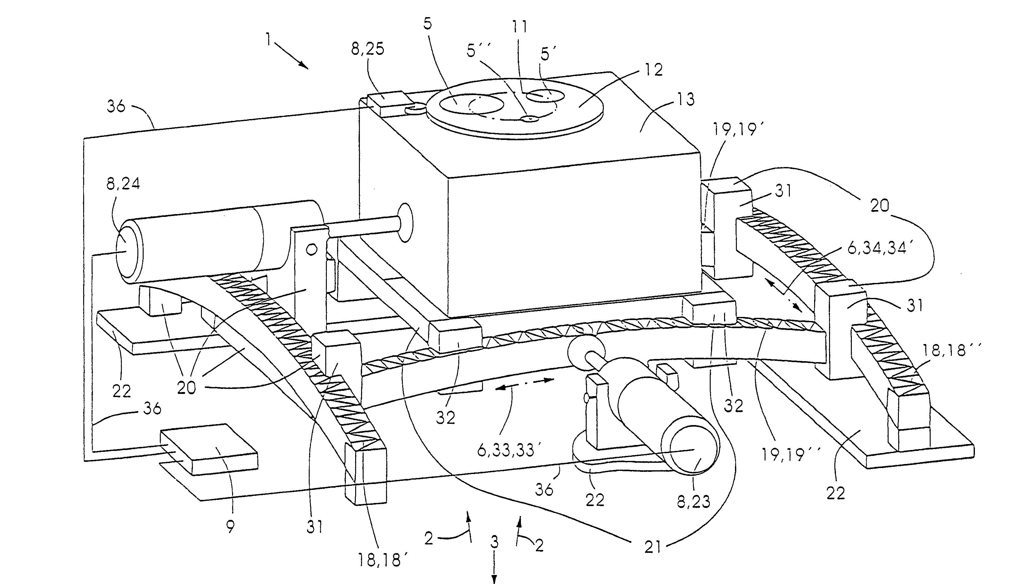
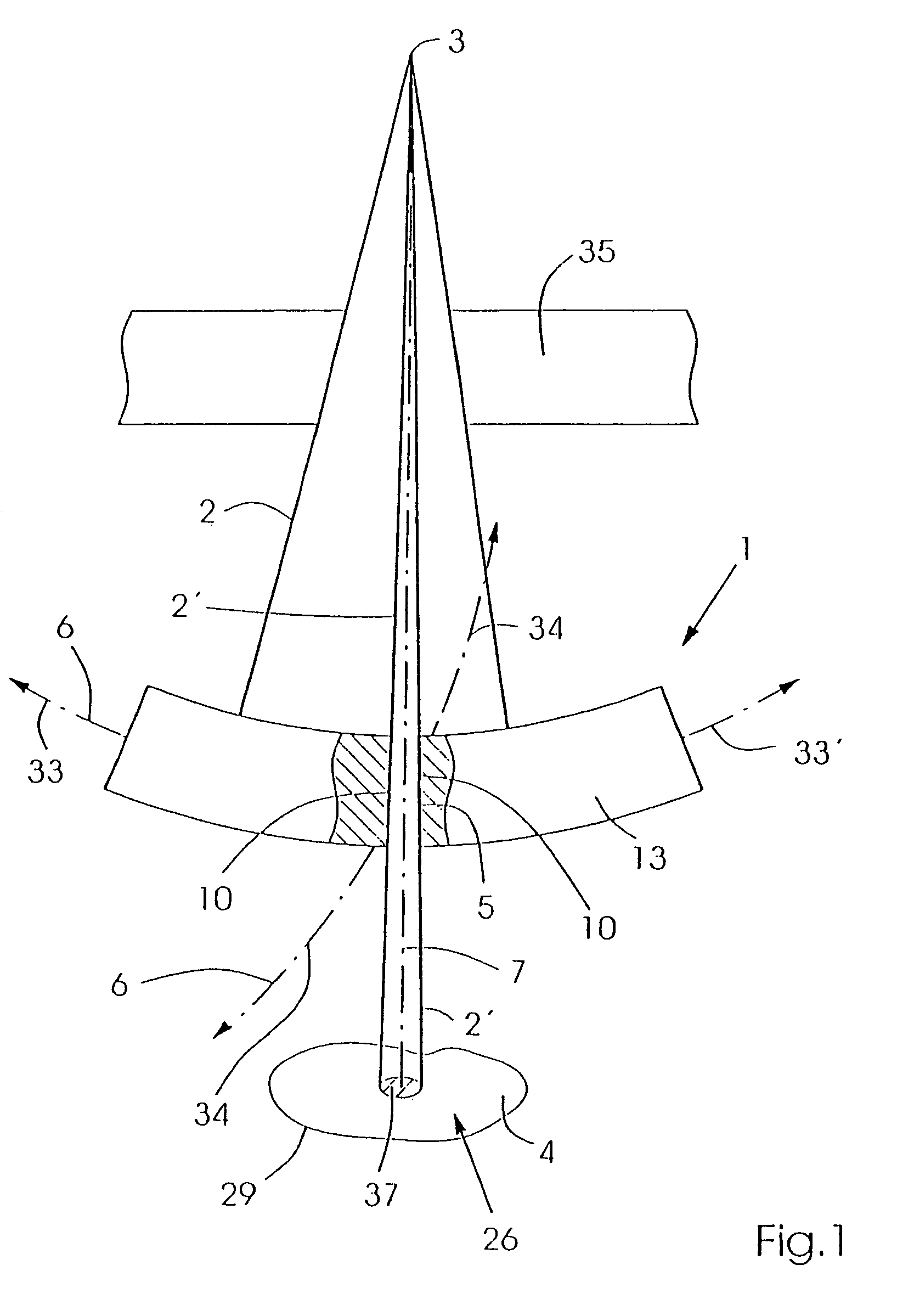
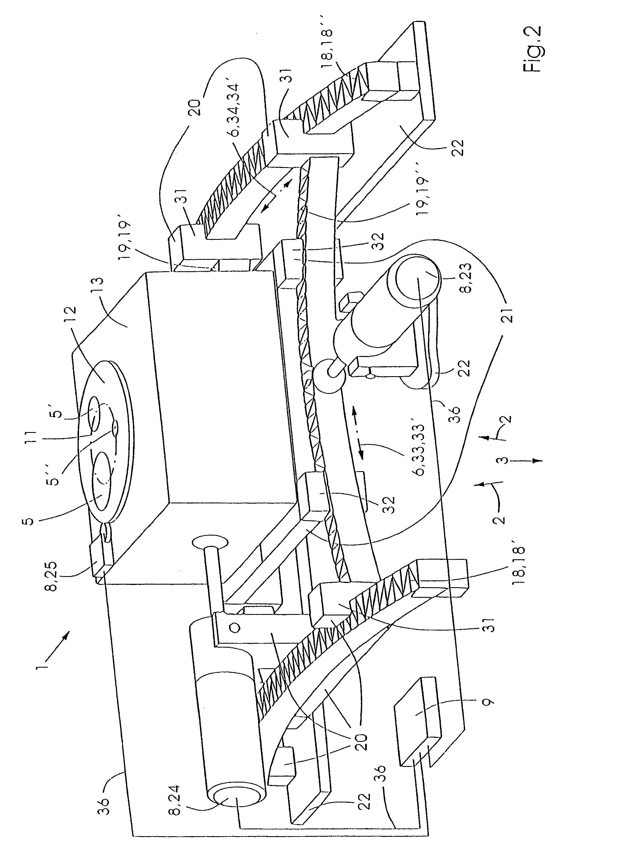
[0041]FIG. 1 shows a basic sketch of a collimator which was further developed in accordance with the invention in that a collimator opening 5 defines the beams 2 emitted by a radiation source 3 such that the beams are incident on a surface 37 which is substantially smaller than the surface 26 of the irradiation to be carried out. The collimator opening 5 is located in a shielding block 13 which can be displaced along a path 6 using a corresponding drive 8 (not shown herein) such that the beam 2′ extending through the collimator opening 5 scans the surface 26 to be irradiated, thereby exposing same to the desired radiation. The radiation surface 26 thereby corresponds to the shape of the object to be treated 4 viewed in the radiation direction 27 of the currently performed radiation, as will be explained in more detail below.

[0042]Some inventive embodiments are included in the drawing. The shielding block 13 with collimator opening 5 is displaced on a spherical surface-shaped path 6,...


PUM


Abstract

The invention relates to a collimator (1) for defining a beam of energetic rays (2) which is emitted from an essentially punctiform radiation source (3) and is oriented onto an object (1) to be treated. The collimator is especially used for the stereotactic conformation radiotherapy of tumors. The collimator (1) is embodied in such a way that an irregular object (4) can be scanned by rays (2, 2′) which are defined by an opening in the collimator. The invention also relates to a program for controlling the collimator. In order to define the contours (29, 29′, 29″) of the objects (4) to be irradiated in a simple but highly accurate manner, especially with a precise definition of the irradiation fields, the collimator comprises a plurality of different sized openings (5, 5′ 5″). One of the openings (5, 5′, 5″) can be selectively displaced in a polydirectional manner on a strip (6) having a spherical surface, and the central axis (7) thereof is oriented towards the radiation source (3). The other collimator openings (5′, 5″) are shielded form the rays (2). A control system (9) acts on the drives (23, 24, 25) of a drive device (8) in such a way that large openings (5, 5′) are used to scan large irradiation surfaces (26) of the object to be treated (4), and small openings (5′, 5″) are used for precise definition at the edge of the irradiation surfaces (26) of the object to be treated (4), especially in the event of irregular contours (29, 29′, 29″).

Description

[0001]This application is the national stage of PCT / EP02 / 11812 filed on Oct. 23, 2002 and claims Paris Convention priority of DE 101 57 523.8 filed Nov. 23, 2001BACKGROUND OF THE INVENTION[0002]The invention concerns a collimator for defining a beam of high energy radiation which is emitted from a substantially punctiform radiation source and directed onto an object to be treated for, in particular, stereotactic conformation radiation of tumors, wherein the collimator is designed to scan an irregular object to be treated with beams which are defined by a collimator opening.[0003]Collimators are used for conform and high-dosed radiation of target volumes having complicated shapes. There are various conventional types of collimators which usually require large amounts of time and / or great technical effort to obtain high accuracy, in particular exact definition of the radiation fields.[0004]Compensators are particularly time-consuming, since a shaped collimator must be produced for eac...

Claims


Application Information

Patent Timeline
Patent Type & Authority Patents(United States)
IPC IPC(8): G21K1/02A61N5/00A61N5/10G21K1/04
CPCG21K1/04G21K1/046A61N5/1042
Inventor PASTYR, OTTOECHNER, GERNOTSCHLEGEL, WOLFGANGHARTMANN
Owner DEUTES KREBSFORSCHUNGSZENT STIFTUNG DES OFFENTLICHEN RECHTS
Why Eureka
Try Eureka