Sheet metal hole cutter

a hole cutter and sheet metal technology, applied in the direction of tool workpiece connection, manufacturing tools, transportation and packaging, etc., can solve the problems of reducing the service life affecting the cutting accuracy of the hole cutter, and the prior art hole saw is not well suited for use as the hole cutter. , to achieve the effect of reducing the cost, reducing the cost, and equal or better cutting performan

Active Publication Date: 2005-09-06
BLACK & DECKER INC
View PDF39 Cites 32 Cited by
  • Summary
  • Abstract
  • Description
  • Claims
  • Application Information

AI Technical Summary

Benefits of technology

[0011]One advantage of the present invention is that the sheet metal hole cutters can be made at significantly less expense than prior art sheet metal hole cutters machined from bar or other metal stock. Further, the hole cutters of the present invention provide equal or better cutting performance and wear life at a significantly reduced cost in comparison to such prior art sheet metal hole cutters.
[0012]Other objects and advantages of the sheet metal hole cutters of the present invention will become more readily apparent in view of the following detailed description of the currently preferred embodiments of the present invention and the accompanying drawings.

Problems solved by technology

One of the drawbacks associated with these types of prior art hole cutters is that they are relatively expensive to manufacture.
For example, machining each hole cutter out of a piece of metal can be a relatively time consuming and expensive process.
These prior art hole saws are not well suited for use as sheet metal hole cutters.
As a result, if such hole saws are used to cut sheet metal, they can be less accurate and have greater total indication run out (“TIR”) than otherwise desired.
Further, such hole saws are designed to cut holes through relatively thick materials, such as wood, and therefore do not have a stop or like feature to prevent the saw from over-feeding through the work piece.
Yet another drawback associated with the use of such hole saws for cutting sheet metal is that the tooth forms do not provide a sufficiently clean or burr-free hole in the work piece, and / or do not provide sufficient clearance between the cutting teeth and the work piece to facilitate smooth and accurate cutting.

Method used


Image

  • Sheet metal hole cutter
  • Sheet metal hole cutter
  • Sheet metal hole cutter

Examples


Embodiment Construction

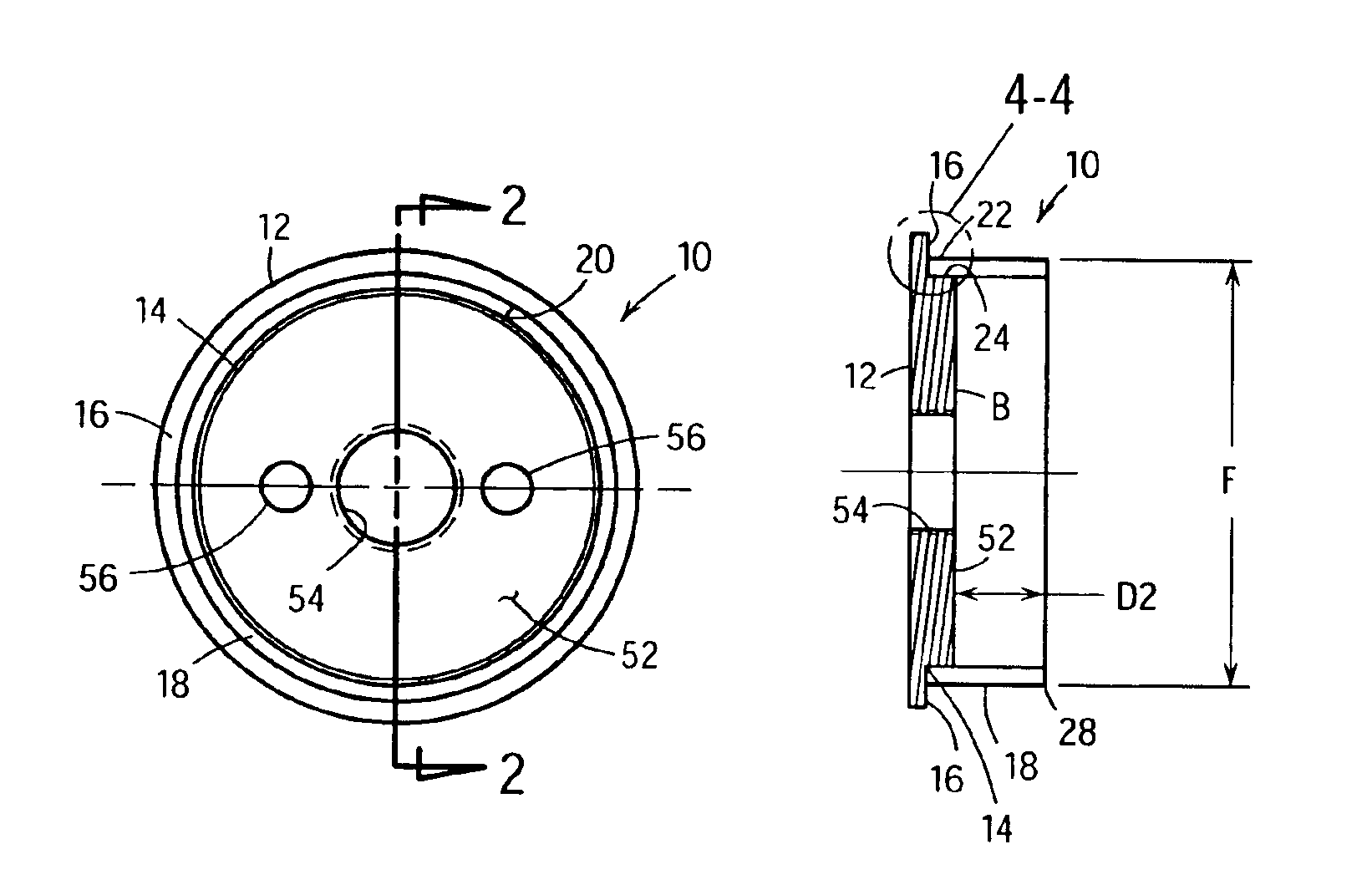
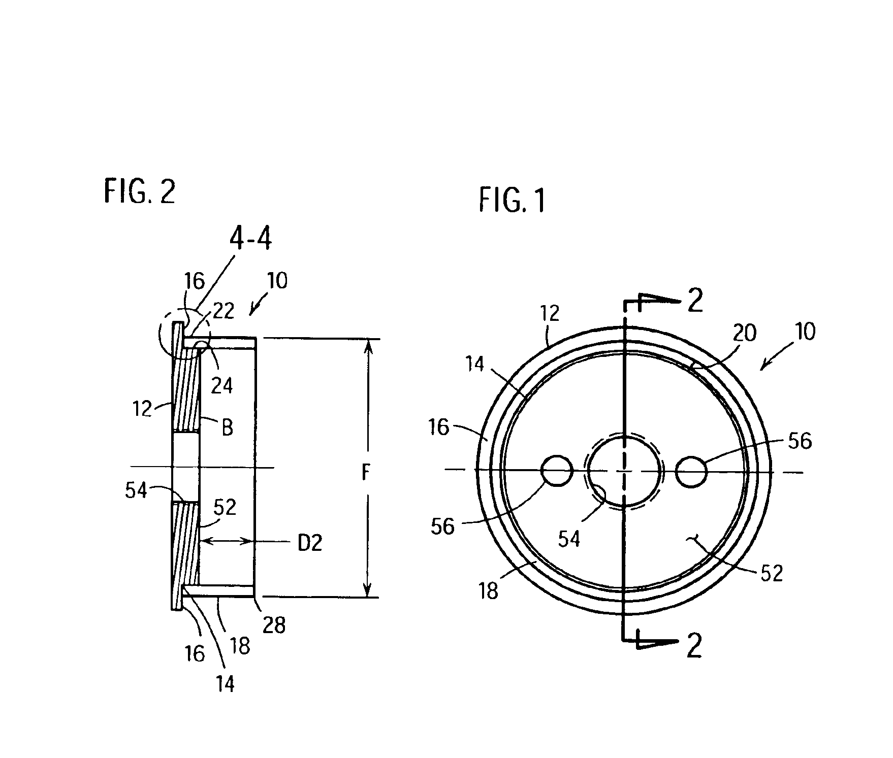
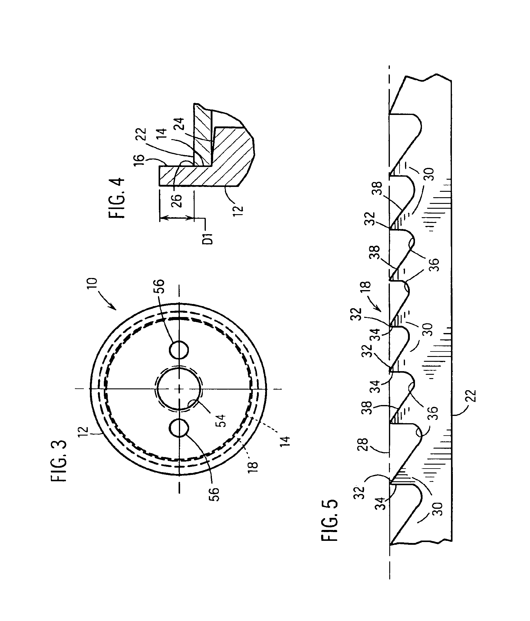
[0022]In FIG. 1, a sheet material hole cutter embodying the present invention is indicated generally by the reference numeral 10. The hole cutter 10 comprises a cap plate 12 defining a substantially circular peripheral groove 14 and an annular shelf 16 extending radially outwardly from the peripheral groove. The hole cutter 10 further comprises an elongated band 18 forming an approximately circular shape with opposite ends of the band contacting each other along a line of joinder 20. The ends of the band are welded together along the line of joinder 20 to form the illustrated closed, circular shape. The band 18 includes a base edge 22 received within the circular peripheral groove 14 in an abutting relationship with an inner edge or shoulder 24 of the groove. An annular weld region 26 is formed between the base edge 22 of the band and the annular shelf 16 of the cap plate 12 to thereby fixedly secure the base edge of the band within the groove. As shown in FIG. 4, the annular shelf ...


PUM

PropertyMeasurementUnit
outer diameteraaaaaaaaaa
acute angleaaaaaaaaaa

Abstract

A sheet metal hole cutter has a cap plate defining a substantially circular peripheral groove and an annular shelf extending radially outwardly from the peripheral groove. An elongated band forming an approximately circular shape with opposite ends of the band contacting each other defines a base edge received within the circular peripheral groove in an abutting relationship with an inner edge of the groove. The band defines an axial depth of about ½ of an inch or less, and an outer diameter within the range of about 9 / 16 of an inch through about 6 inches. A weld region fixedly secures the base edge of the band to the cap plate. The annular shelf of the cap plate extends radially outwardly from the base edge of the band and defines a radial depth of at least approximately 1 / 16 of an inch in order to prevent over-feeding of the hole cutter through a work piece. A plurality of teeth are disposed along a cutting edge of the band, and each tooth defines a cutting surface extending between an outer edge and an inner edge of the tooth. Each cutting surface is oriented at an acute angle relative to the plane of the cap plate such that the outer edge of the respective tooth is spaced further away from the cap plate than the inner edge to thereby preferentially cut the work piece with the outer edge and create a substantially burr-free hole in the work piece.

Description

CROSS-REFERENCE TO RELATED APPLICATIONS[0001]This application claims priority to U.S. Provisional Patent Application No. 60 / 479,664, filed Jun. 18, 2003, the disclosure of which are incorporated herein by reference.FIELD OF THE INVENTION[0002]The present invention relates to apparatus and methods for cutting holes, and more particularly, to sheet metal hole cutters having circular metal bands welded to cap plates and defining cutting edges having pluralities of cutting teeth for cutting holes in sheet metal and other sheet-like materials.BACKGROUND INFORMATION[0003]Typical prior art sheet metal hole cutters comprise a circular base, a peripheral wall formed on one side of the base and extending axially therefrom, and a plurality of cutting teeth machined in the outer edge of the peripheral wall. The base, peripheral wall and cutting teeth are machined from a piece of steel to form a hole cutter of unitary construction. Exemplary sheet metal hole cutters of this type are sold by Miya...

Claims


Application Information

Patent Timeline
Patent Type & Authority Patents(United States)
IPC IPC(8): B23B51/04B23B
CPCB23B51/0406B23B51/0473B23B2222/28Y10T408/8957B23B2251/285B23B2251/54Y10T408/895B23B2240/16B23B51/0411B23B51/04
Inventor KORB, WILLIAM B.DOUGLAS, BRIAN K.HALL, KENNETH
Owner BLACK & DECKER INC
Why Eureka
Try Eureka