Directional patch antenna

a patch antenna and antenna technology, applied in the field of antenna units, can solve the problems of sensitive antenna reception, limited antenna reception, and a large portion of antenna reception becoming useless

Inactive Publication Date: 2006-11-07
DELPHI TECH INC
View PDF4 Cites 36 Cited by
  • Summary
  • Abstract
  • Description
  • Claims
  • Application Information

AI Technical Summary

Problems solved by technology

Thus, the mounting location for SDARS patch antennas makes antenna reception a sensitive issue with respect to the position of the antenna on the vehicle.
Even further, although patch antenna circular polarization patterns are generally omni-directional in the azimuth plane so that reception does not favor any particular direction, antenna reception may be limited due to antenna position relative to the vehicle.
As a result, some portion of the antenna's reception becomes useless and thereby limits the functionality of the antenna.
Thus, when mounted inside a vehicle, conventional patch antennas have inherent performance issues relating to directionality of the reception.

Method used


Image

  • Directional patch antenna
  • Directional patch antenna
  • Directional patch antenna

Examples


Embodiment Construction

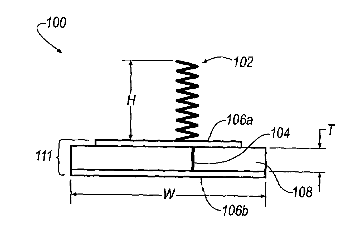
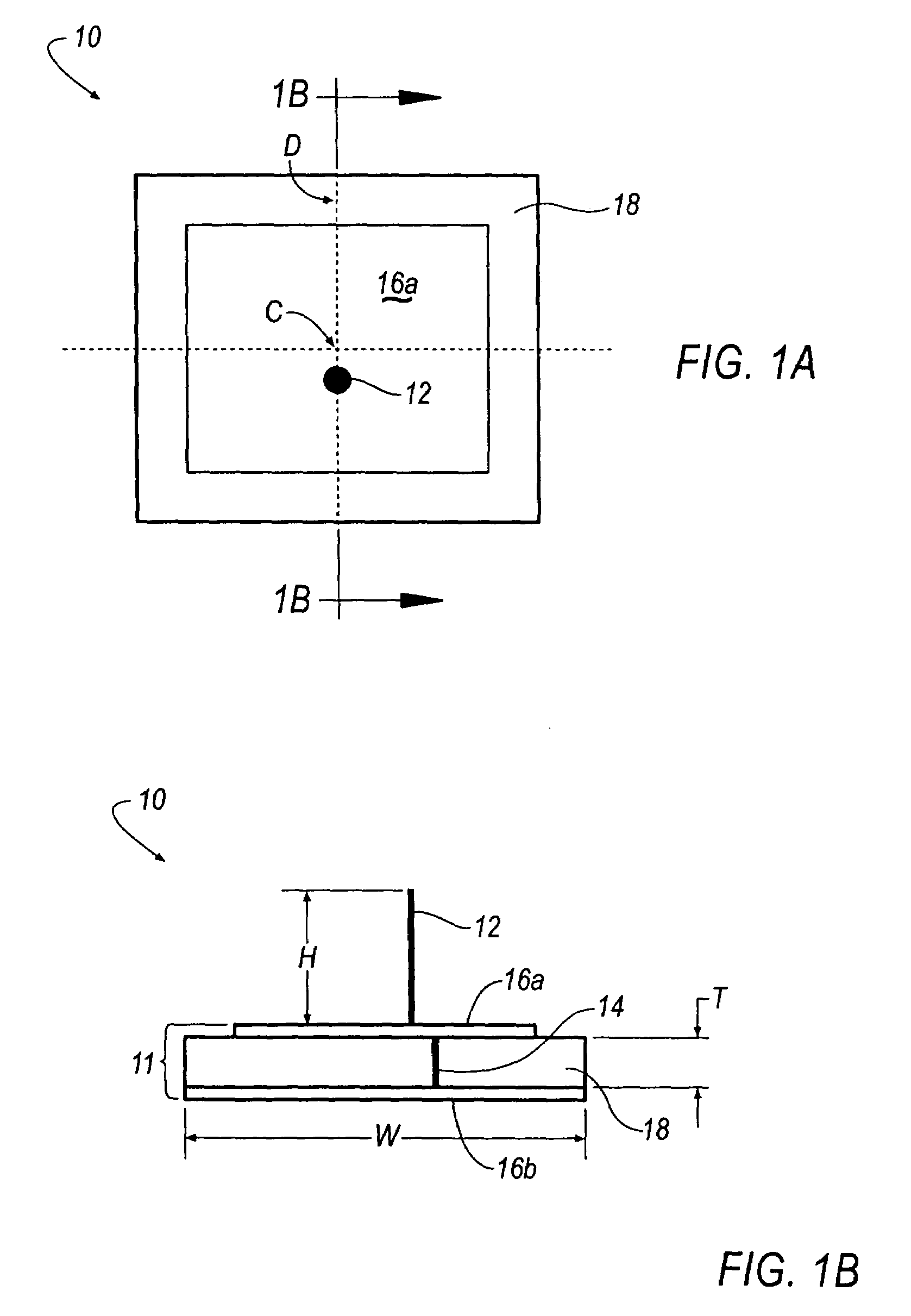
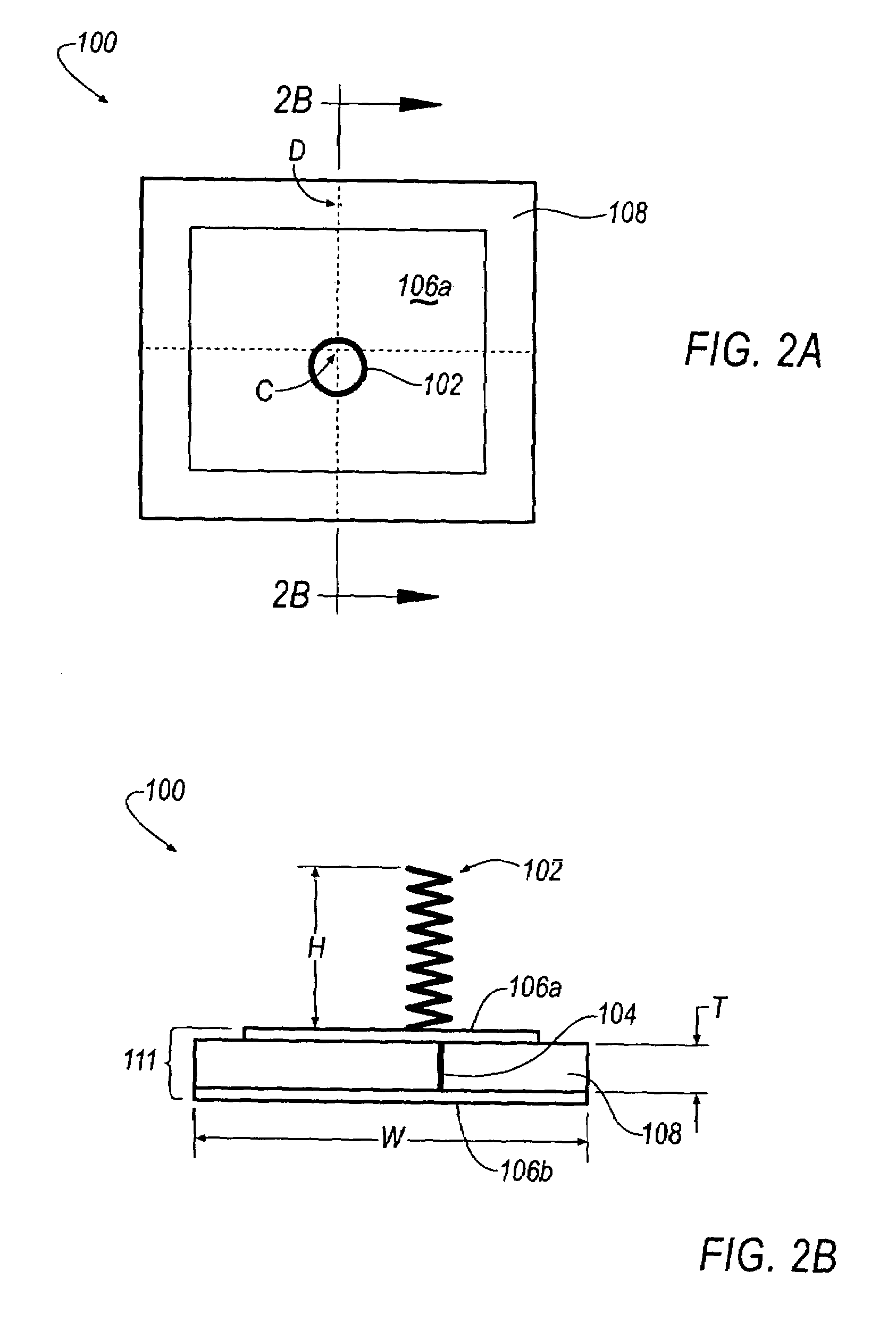
[0018]The above described disadvantages are overcome and a number of advantages are realized by the inventive antenna unit, which is generally illustrated at 10, 100, 200, 300 in FIGS. 1A–4B. Essentially, the antenna unit 10, 100, 200, 300 improves directional linear polarization patterns at low-elevation angles, particularly at 0°, of a wire antenna element 12, 102, 202, 302 while maintaining circular polarization characteristics of a patch antenna element 11, 111, 211, 311. Referring initially to FIGS. 1A and 1B, the antenna unit 10 generally includes a straight-wire antenna element 12 soldered to a patch antenna element 11. The patch antenna element 11 includes a single feed pin 14 (FIG. 1B) extending through a high dielectric substrate 18 that electrically couples a bottom metallization 16b to a top metallization 16a where the straight-wire antenna element 12 is soldered. The top and bottom metallizations 16a, 16b may include any desirable metallization, such as, for example, a ...


PUM


Abstract

An antenna unit is disclosed. The antenna unit includes a wire antenna element and a patch antenna element. The wire antenna element creates a null at low-elevation angles to provide directional antenna patterns in azimuth planes. Nulls of the terrestrial signal pattern are directed toward the passenger compartment of a vehicle to create a larger spatial region for reception of terrestrial signals.

Description

TECHNICAL FIELD [0001]The present invention generally relates to an antenna unit that has directional reception capabilities.BACKGROUND OF THE INVENTION [0002]It is known in the art that automotive vehicles are commonly equipped with audio radios that receive and process signals relating to amplitude modulation / frequency modulation (AM / FM) antennas, satellite digital audio radio systems (SDARS) antennas, global positioning system (GPS) antennas, digital audio broadcast (DAB) antennas, dual-band personal communication systems digital / analog mobile phone service (PCS / AMPS) antennas, Remote Keyless Entry (RKE) antennas, Tire Pressure Monitoring System antennas, and other wireless systems.[0003]Currently, it is known that patch antennas are employed for reception of GPS [i.e. right-hand-circular-polarization (RHCP) waves] and SDARS [i.e. left-hand-circular-polarization (LHCP) waves]. SDARS patch antennas may be considered to be a ‘single element’ antenna that incorporates performance ch...

Claims


Application Information

Patent Timeline
Patent Type & Authority Patents(United States)
IPC IPC(8): H01Q21/00H01Q9/04H01Q21/29
CPCB60C23/0444H01Q9/0407H01Q21/29
Inventor YEGIN, KORKUTLIVENGOOD, WILLIAM R.SNOEYINK, RANDALL J.
Owner DELPHI TECH INC
Why Eureka
Try Eureka