Micro-display engine

a micro-display engine and engine body technology, applied in the field of micro-display engines, can solve the problems of inefficient loss of image light, loss of some light from the image source, loss of some on-axis ambient light, etc., and achieve the effects of improving the efficiency and performance of micro-display engines, enhancing viewing performance, and improving us

Active Publication Date: 2006-11-07
TDG ACQUISITION COMPANY
View PDF33 Cites 23 Cited by
  • Summary
  • Abstract
  • Description
  • Claims
  • Application Information

AI Technical Summary

Benefits of technology

[0011]The invention among its various embodiments provides for improving the efficiency and performance of micro-display engines by making better use of image light and by separately regulating the admission of ambient light. Polarization management is used for conserving image light, for regulating the admission of ambient light, and for directing image light among multiple surfaces for enhancing viewing performance. Polarizing components associated with image sources can be incorporated into other optical components of the display to reduce the number of components, simplify the requirements of imaged surfaces, and avoid imaging errors associated with imaging polarizing components. Improved efficiencies, performance enhancements, and cost and weight reductions are made possible by the application of the various embodiments of the invention.
[0013]Although both the image light and the admitted ambient light are superimposed along the viewing axis, the ambient light reaches the beamsplitter independently of the reflective focusing optic. Accordingly, the reflective focusing optic can be made fully reflective to conserve the image light. The ambient light can be separately transmitted to the beamsplitter without substantial loss.
[0015]The non-immersive display can also include an ambient-light-admitting adjuster that regulates the amount of ambient light transmitted between the ambient-light-admitting aperture and the viewing aperture along the viewing axis. Preferably, both the beamsplitter and the ambient-light-admitting aperture are polarization sensitive, and the ambient-light-admitting adjuster varies polarization sensitivities between the beamsplitter and the ambient-light-admitting aperture. For example, both the beamsplitter and the ambient-light-admitting aperture can be associated with polarizers, and the ambient-light-admitting adjuster varies a relative angular orientation of the aperture polarizer with respect to the beamsplitter polarizer. A phase adjuster can be used for rotating polarization of the image light transmitted through the polarization-sensitive beamsplitter en route to and from the reflective focusing optic to improve the efficiency of the required transmissions and reflections performed by the beamsplitter.
[0017]Another non-immersive virtual display in accordance with the invention includes a housing having an ambient-light-admitting aperture and a viewing aperture, an image source, and a reflector. The housing encloses optical transmissions along different optical pathways including transmissions of image light from the image source to the reflector along a first optical pathway and transmissions of ambient light from the ambient-light-admitting aperture to the viewing aperture along a second optical pathway. A beamsplitter located at an intersection of the first and second optical pathways supports the transmissions of image light and ambient light along the first and second pathways, and also supports reflection of the transmitted image light from the reflector to the viewing aperture for combining the transmitted image light with the transmitted ambient light along the second optical pathway.
[0026]The display engine can also include a housing having both a viewing aperture and an ambient-light-admitting aperture aligned in the second direction. An ambient-light-admitting adjuster can be used to regulate the amount of ambient light transmitted between the ambient-light-admitting aperture and the viewing aperture along the second direction.
[0039]The reflective optics can take a variety of forms for contributing to the production of the virtual image. For example, one of the reflective optics can have a nominally planer reflective surface and the other of the reflective optics can have a non-planar reflective surface. Alternatively, both of the reflective optics can have non-planer reflective surfaces for contributing to the magnification of the virtual image. At least one of the reflective optics can have an aspheric reflective surface for contributing to a focusing function for enhancing a view of the virtual image.

Problems solved by technology

The partial reflectivity results in the loss of some light from the image source.
The partial transmissivity results in the loss of some on-axis ambient light.
The loss of image light is inefficient, requiring a higher output image source.
The loss of ambient light may also be of concern.
Views transmitted by ambient light through the partially reflective focusing optics can also be undesirably distorted by passage through the partially reflective focusing optics.

Method used


Image

  • Micro-display engine
  • Micro-display engine
  • Micro-display engine

Examples


Embodiment Construction

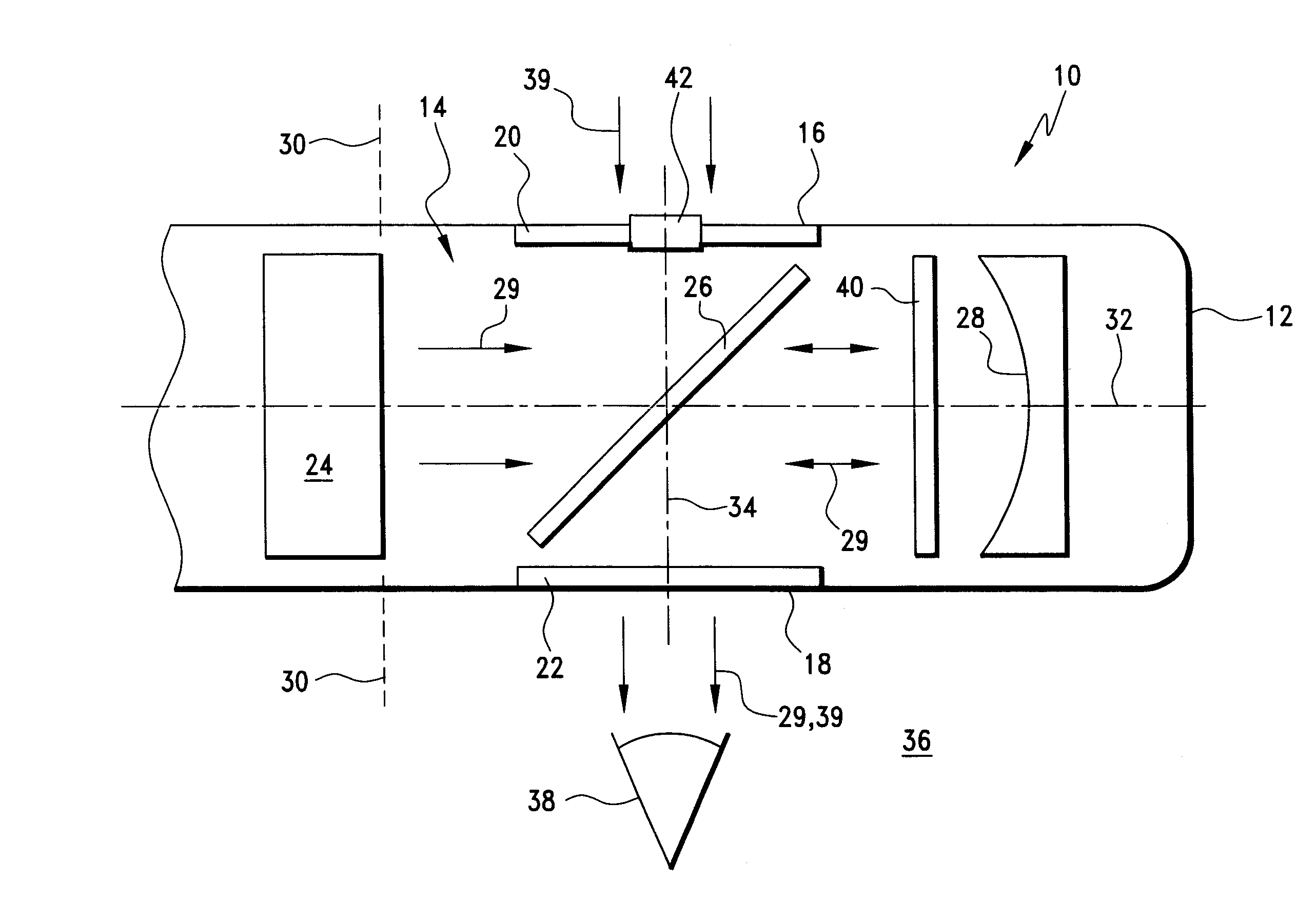
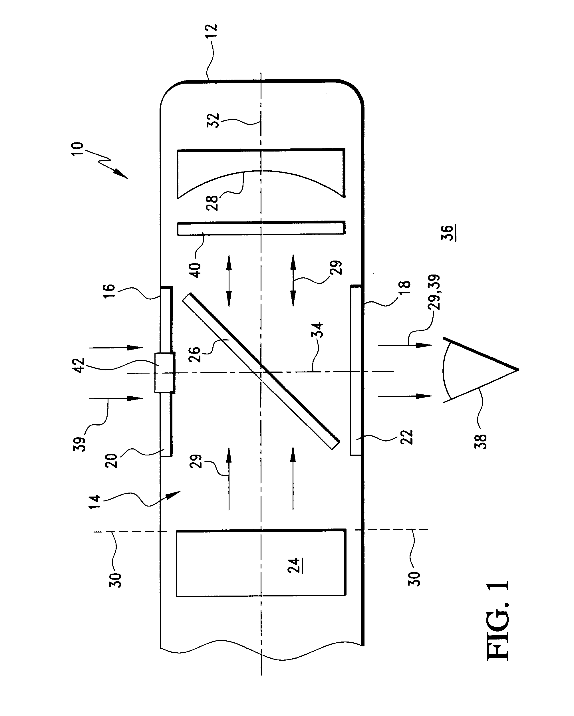
[0044]A non-immersive display 10 of the type especially suitable for use in portable display devices such as head-mounted viewers is depicted in FIG. 1. A housing 12 of the display (only part of which is shown in FIG. 1) supports and provides any required shrouding for a micro-display engine 14. For example, the housing 12 can be molded into a form that provides for locating, mounting, and enclosing components of the micro-display engine 14 and also provides for limiting or excluding the ingress of unwanted environmental light into the optical pathways of the micro-display engine 14 or into the viewing path of an observer. Typical of head-mounted displays, the housing can be fashioned in the form of one or more eyecups.

[0045]In the non-immersive embodiment depicted in FIG. 1, limited amounts of ambient environmental light are admitted into the housing 12 through an ambient-light-admitting aperture 16. Images produced within the housing 12 can be viewed through a viewing aperture 18 ...


PUM


Abstract

Virtual displays with micro-display engines are arranged in compact, lightweight configurations that generate clear virtual images for an observer. The displays are particularly suitable for portable devices, such as head-mounted displays adapted to non-immersive or immersive applications. The non-immersive applications feature reflective optics moved out of the direct line of sight of the observer and provide for differentially modifying the amount or form of ambient light admitted from the forward environment with respect to image light magnified within the display. Micro-display engines suitable for both non-immersive and immersive display applications and having LCD image sources displace polarization components of the LCD image sources along the optical paths of the engines for simplifying engine design. A compound imaging system for micro-display engines features the use of reflectors in sequence to expand upon the imaging possibilities of the new micro-display engines. Polarization management also provides for differentially regulating the transmission of ambient light with respect to image light and for participating in the image formation function of the image source.

Description

BACKGROUND OF THE INVENTION[0001]1. Field of the Invention[0002]The invention relates to micro-display engines, particularly for portable displays, such as head-mounted viewers. Typically, the micro-display engines feature compact image generators that output real images and magnifying optics that produce enlarged virtual images.[0003]2. Description of Related Art[0004]Micro-display engines can be incorporated into a variety of devices and are particularly suitable for portable devices including hand-held, wrist-worn, or head-mounted devices. For example, the micro-display engines can be used in pagers, wireless mobile telephones, or wrist-worn computers or can be mounted in various types of viewers for displaying data, graphics, or video.[0005]Among the known devices, single micro-display engines are used in monocular viewers or biocular viewers, which provide dual images of the same image sources, and pairs of micro-display engines are used in binocular viewers. All three types of...

Claims


Application Information

Patent Timeline
Patent Type & Authority Patents(United States)
IPC IPC(8): G02B27/10G02B27/14G09G5/00G02B5/30G02B27/00G02B27/01
CPCG02B27/0172G02B27/144G02B27/16G02B5/30G02B2027/011G02B2027/0118
Inventor TRAVERS, PAUL J.
Owner TDG ACQUISITION COMPANY
Why Eureka
Try Eureka