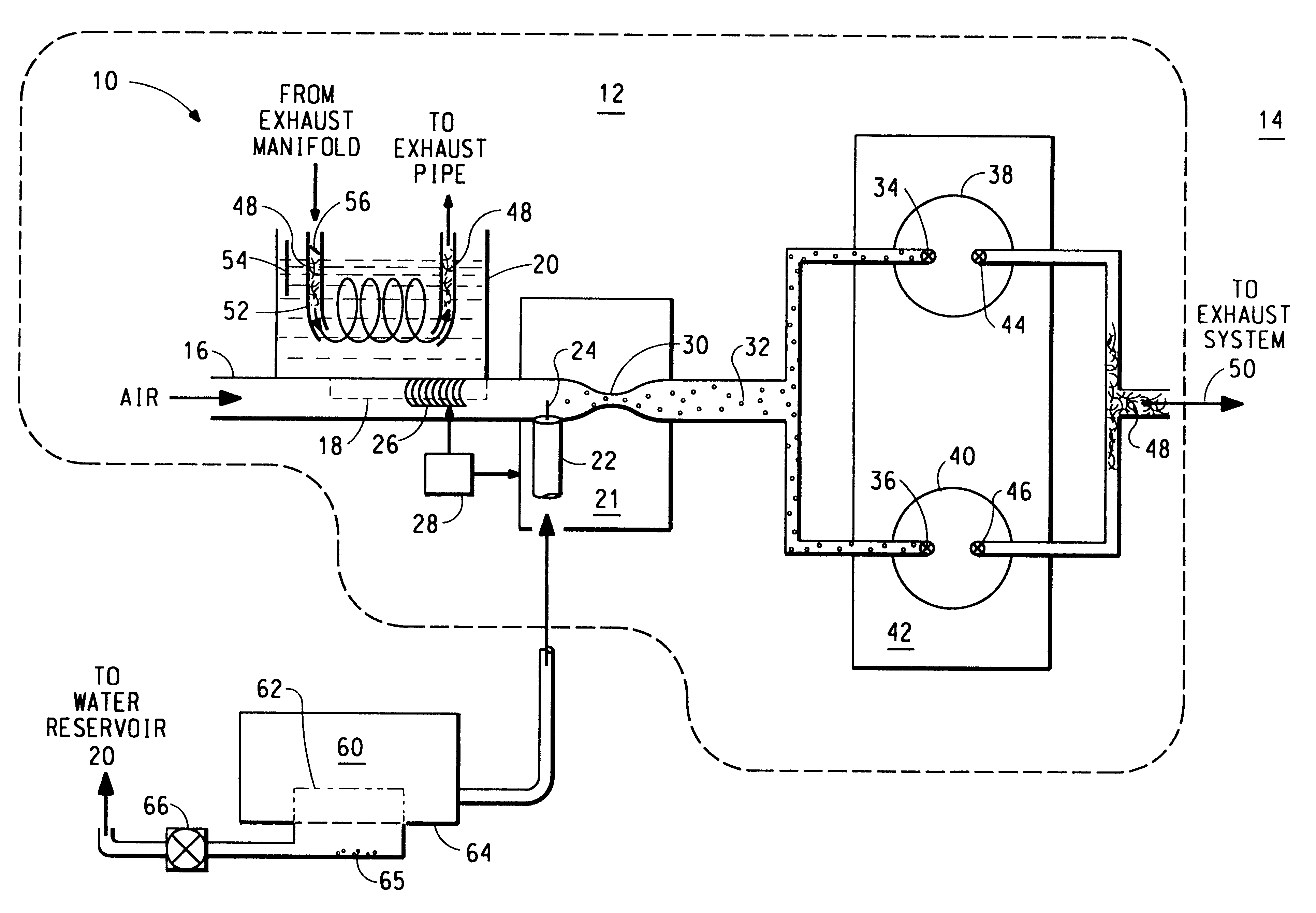
Humidifying gas induction or supply system

a gas induction or supply system technology, applied in the field of humidification gas induction or supply system, can solve the problems of complex system, high implementation cost, and large implementation cost, and place a significant constraint on potential implementation

Inactive Publication Date: 2003-01-28
DESIGN TECH & INNOVATION
View PDF23 Cites 28 Cited by
  • Summary
  • Abstract
  • Description
  • Claims
  • Application Information

AI Technical Summary

Problems solved by technology

However, the complexity of such a system and the high cost of its implementation have conspired to outweigh the benefits obtained by the process for large-scale commercialization.
More specifically, water injection s

Method used


Image

  • Humidifying gas induction or supply system
  • Humidifying gas induction or supply system
  • Humidifying gas induction or supply system

Examples


second embodiment

In the invention there is provided a fuel cell comprising a humidifying gas induction or supply system having a hydrophilic membrane, particularly a proton exchange membrane fuel cell.

Proton exchange membrane fuel cells function by combining hydrogen and atmospheric or pure oxygen with the aid of a catalyst, generating useful electricity and water as a by-product across a proton exchange membrane and over a catalyst. Hydrogen functions as the anode and atmospheric or pure oxygen as the cathode. The current carrier that flows across the proton exchange membrane for the process of generating electricity is in the form of protons. For the proton exchange membrane to function effectively, it needs to be kept moist, because water is needed to transport these protons across it (as H.sub.3 O.sup.+, rather than H.sup.+) and so generate a current. Therefore, the higher the relative humidity of the induction gases into a fuel cell, the greater the efficiency of this energy conversion device i...


PUM

PropertyMeasurementUnit
Surface areaaaaaaaaaaa
Hydrophilicityaaaaaaaaaa
Vapor pressureaaaaaaaaaa

Abstract

Water vapor is introduced into an inlet air stream (16) of an engine (12), for example, by a pervaporation process through a non-porous hydrophilic membrane (18). A water reservoir (20), which can contain contaminated water, provides a vapor pressure gradient across the hydrophilic membrane (18) into the inlet air stream (16), while the rate of delivery of the water vapor to a cylinder (38-40) is self-regulated by the rate of flow of air across the membrane. The hydrophilic membrane (18) therefore also filters the water from the water reservoir (20) to an extent that pure water vapor is provided to the air inlet stream (16). Delivery of water vapor can nevertheless be controlled using a hood (26) that slides over the hydrophilic membrane to limit its exposed surface area. Alternatively, water vapor is introduced into one or more of the gas streams of a fuel cell by separating the gas stream from the wet exhaust gas stream by a hydrophilic membrane such that moisture passes across the membrane to moisten the gas stream and thereby prevent drying out of the proton exchange membrane.

Description

BACKGROUND TO THE INVENTIONThis invention relates, in general, to humidifying gas induction or supply systems and particularly, but not exclusively, to a humidifying air induction or supply system of an internal combustion engine and a humidifying gas induction or supply system for a fuel cell.SUMMARY OF THE PRIOR ARTIn energy conversion systems in general, a fuel and an oxidant are combined to provide energy. In this process, chemical energy is converted into kinetic energy or electricity, as well as heat.In internal combustion engines, including two-stroke, four-stroke, rotary and diesel motors for example, fuel-air mixtures are burnt to provide this chemical energy. Prior to combustion, the fuel may be dispersed into the induction air stream by means of direct injectors or by a carburetor, and the combustion itself may be triggered by an electrical spark, a glow-wire or simply by the heat of compression of the fuel-air mixture. In all internal combustion engines, the sudden incre...

Claims


Application Information

Patent Timeline
IPC IPC(8): H01M8/04B01D69/08F02M25/032F02B47/04F02M25/022F02M25/028F23C99/00F23L7/00F24F6/00H01M8/10
CPCH01M8/04119F02M25/028F02M25/0224H01M8/04156H01M2300/0082Y02T10/121Y02E60/50Y02T10/12
Inventor TONKIN, MARK CHRISTOPHERYOUNG, MARK ANDREWSCHUCHARDT, MARK ELDEN
Owner DESIGN TECH & INNOVATION
Why Eureka
Try Eureka