Optical disk apparatus and optical disk processing method

a technology of optical disk and optical disk, applied in the field of optical disk apparatus, can solve the problems of easy change of floating amount, stricter specifications, collision of objective lens with optical disk, etc., and achieve the effect of stable focus control and focus lead-in operation

Inactive Publication Date: 2006-11-07
KK TOSHIBA
View PDF22 Cites 10 Cited by
  • Summary
  • Abstract
  • Description
  • Claims
  • Application Information

AI Technical Summary

Benefits of technology

[0013](1) an optical disk apparatus which can realize stable focus control and focus lead-in operation even when a high-NA optical system is used; and
[0014](2) an optical disk processing method which can realize stable focus control and focus lead-in operation even when a high-NA optical system is used.

Problems solved by technology

When the optical NA is increased, problems of stricter specifications of the tilt of an objective lens and a short distance between the objective lens and optical disk surface are pointed out.
When the objective lens and optical disk adjoin via such a short distance, the most serious problem is a collision of the objective lens against the optical disk.
However, in this method, since the floating force of the objective lens with respect to the optical disk changes depending on the rotational speed of the disk, the floating amount readily changes due to the influences of disk rotation variations.
When the rotational speed of the disk is not constant, the objective lens becomes unstable in this control method.
However, when scratches, dust, fingerprints, and the like become attached to the disk surface, the amplitude of the focus error signal itself used as a servo signal becomes small, the signal is susceptible to disturbances, and so forth.
Furthermore, when the NA is high, since the spot size on the disk surface becomes small, the signal is readily influenced by disturbances, and the focus servo consequently runs away.
Such an unstable state similarly occurs even in a focus lead-in operation, thus disturbing a stable focus lead-in operation.
That is, since two different focus errors are generated using return light from a single optical spot formed on the information recording surface of the optical disk, an unstable state of the optical spot formed by a high-NA optical system cannot be avoided.
As a result, the conventional servo control is vulnerable to disturbances that depend on the surface state of the optical disk such as scratches, dust, fingerprints, and the like, and the focus servo readily runs away due to the influences of disturbances.
Once the servo runs away, the objective lens may collide against the disk to damage not only the optical disk but also the objective lens, and information recording / reproduction may be disabled.
As described above, when the conventional focus error detection circuit is applied to a high-NA optical system, the objective lens is highly likely to collide against the disk.
Also, the focus servo itself inevitably runs away due to the influence of scratches, dust, and fingerprints attached to the disk.
Furthermore, in the case of a high-density optical disk having a two-layered information recording surface, a focus error detection range is inevitably narrowed down.
For this reason, focus control performance deteriorates.
When focus control fails, the objective lens inevitably collides against the optical disk.

Method used


Image

  • Optical disk apparatus and optical disk processing method
  • Optical disk apparatus and optical disk processing method
  • Optical disk apparatus and optical disk processing method

Examples


first embodiment

[0038]Two objective lens actuators are provided, and focus lead-in control is performed by learning the surface run-out.

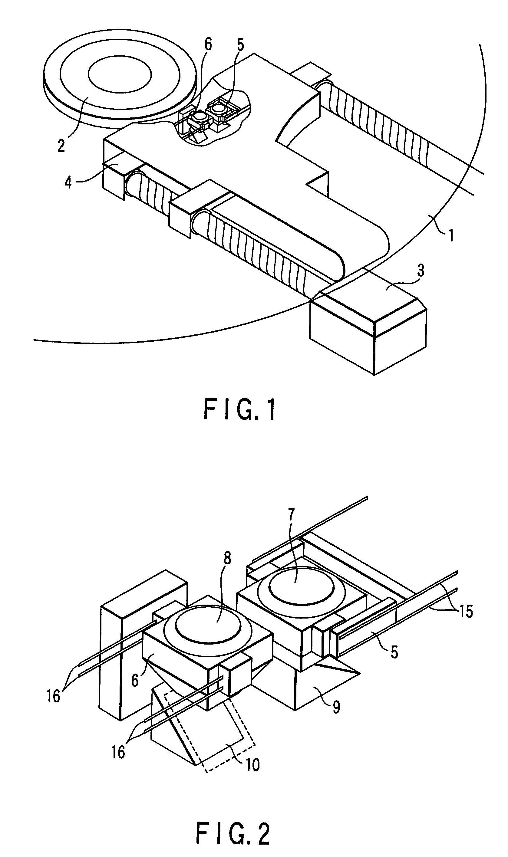
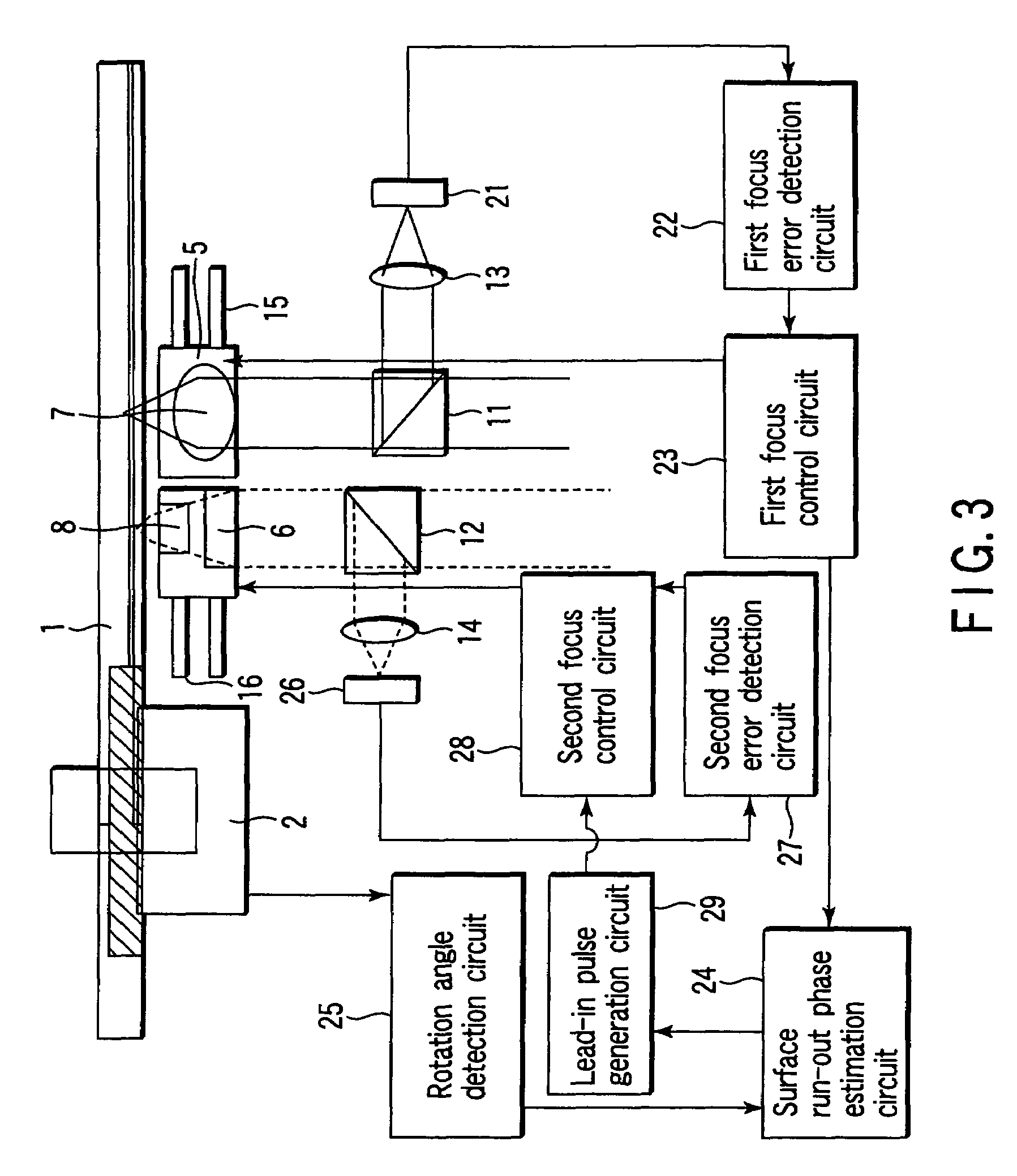
[0039]FIG. 1 is a perspective view showing the structure of an optical disk apparatus having a focus error detection circuit according to the present invention. FIG. 2 is an enlarged view of the structure around an objective lens actuator. This structure has two different optical systems, and an optical head has two objective lenses and actuators, so that information can be reproduced from or recorded on a predetermined optical disk using a low-NA optical system, and information can be reproduced from or recorded on another predetermined optical disk using a high-NA optical system.

[0040]An optical disk 1 having an information recording surface is attached to a spindle motor 2, and its rotation is controlled. An optical head for reproducing / recording information by forming an optical spot on the information recording surface of the optical disk 1 is supported to be ...

second embodiment

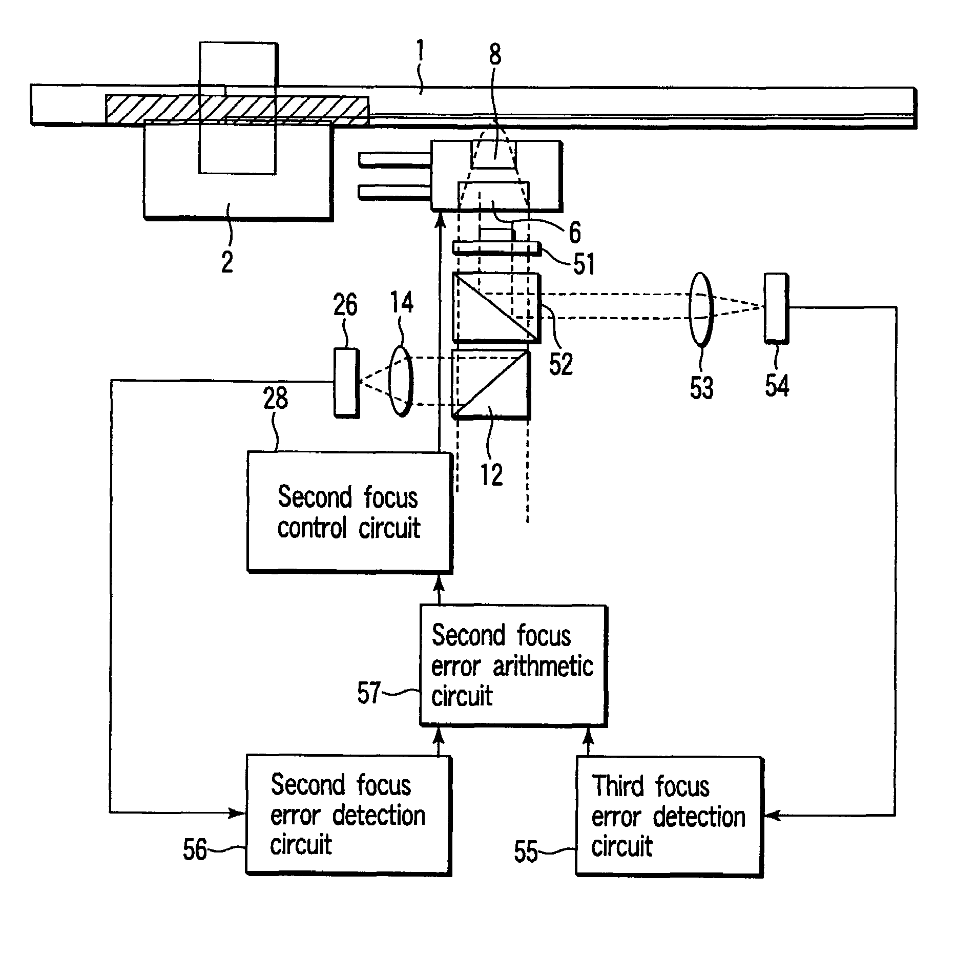
[0056]A focus error detection optical system generates and mixes two focus errors.

[0057]FIG. 8 is a block diagram showing the arrangement of an optical disk apparatus having a focus error detection circuit of the present invention. Since the arrangement of the low-NA first optical system and the like is the same as that of the first embodiment, FIG. 8 shows the arrangement of only the high-NA second optical system.

[0058]In this arrangement, a phase converter 51 having a function of shifting about ¼λ (wavelength) only the transfer phase around the optical axis center is inserted in the optical path of the high-NA optical system. Some light components of light that enter the second objective lens 8, especially, light components near the optical axis center are not focused by a first component lens 62 that forms the second objective lens, but are focused by only a second component lens 61, forming a spot on the information recording surface in the optical disk. FIG. 9 shows the structu...


PUM

PropertyMeasurementUnit
thicknessaaaaaaaaaa
thicknessaaaaaaaaaa
distanceaaaaaaaaaa

Abstract

An optical disk apparatus has a first optical system having an objective lens with a first NA, a second optical system having an objective lens with a second NA lower than the first NA, an addition mechanism for adding focus error signals detected by the first and second optical systems, and an alignment mechanism for aligning the objective lens in accordance with the addition result of the addition mechanism.

Description

CROSS-REFERENCE TO RELATED APPLICATIONS[0001]This application is a divisional application of U.S. Ser. No. 09 / 916,444, filed Jul. 30, 2001, now U.S. Pat. No. 6,829,203 the entire contents of which are incorporated herein by reference. This application is based upon and claims the benefit of priority from the prior Japanese Patent Application No. 2001-126115, filed Apr. 24, 2001, the entire contents of which are incorporated herein by reference.BACKGROUND OF THE INVENTION[0002]The present invention relates to an optical disk apparatus for recording information on or reproducing information from an information recording track of an optical disk by irradiating the optical disk with a light beam. More particularly, the present invention relates to focus error detection of a light beam in this optical disk apparatus. Also, the present invention relates to an optical disk processing method.[0003]In recent years, various studies and developments have been made for the purpose of improving ...

Claims


Application Information

Patent Timeline
Patent Type & Authority Patents(United States)
IPC IPC(8): G11B7/00G11B7/095G11B7/085G11B7/09G11B7/135G11B7/14
CPCG11B7/0945G11B7/0956G11B7/13927G11B7/08511G11B7/0943G11B7/0948G11B2007/0006G11B2007/0013G11B2007/13727
Inventor YONEZAWA, MINORUOHSAWA, HIDEAKI
Owner KK TOSHIBA
Why Eureka
Try Eureka