
Data communications system

a data communication and data technology, applied in the field of data communication systems, can solve the problems of insufficient communication quality, large variation in transfer delay on the receiving side, and information of this data link layer cannot be used simply by encapsulating a packet, and achieve the effect of high quality

Inactive Publication Date: 2006-11-07
FUJITSU LTD
View PDF3 Cites 113 Cited by
  • Summary
  • Abstract
  • Description
  • Claims
  • Application Information

AI Technical Summary

Benefits of technology

The present invention provides a data communications system for transmitting data with a known data structure in a high-quality manner using a network protocol. The system allows for synchronous communications and can handle data loss and modification of the transfer order. It also allows for a plurality of physically independent networks to be used for transferring data. The system includes a transmitting side relay device and a receiving side relay device, with additional information generation means, separation means, analysis means, reproduction means, and transmitting means for generating and transmitting a relay transfer unit. The system can be used for high-speed data transfer and can handle data loss and modification of the transfer order.

Problems solved by technology

However, since UPS is provided only with an error detection mechanism as far as a mechanism for maintaining transfer quality is concerned, the loss and redundancy of an IP-encapsulated packet, the modification of an arrival order on the receiving side, etc., must be coped with by an application software program on both the transmitting and receiving sides.
Therefore, when the digital video data are reproduced, there is the possibility that there may be some failure and thereby sufficient communication quality cannot be expected.
However, in a “best-effort” type network, such as the Internet, both transfer rate and transfer delay vary depending on the traffic of a network and simultaneously, transfer delay on the receiving side greatly varies depending on the loss and redundancy of an IP-encapsulated packet.
However, the information of this data link layer cannot be used simply by encapsulating a packet transferred in an individual network, including information about the functions of a data link layer or less.
However, since the IEEE1394 standard presumes that a receiving node exists within a prescribed cable length, a time allowed until a reply packet is returned to an asynchronous packet is very short.
Therefore, if the reply packet is transmitted after an asynchronous packet is actually received, delivery confirmation cannot be normally completed in an asynchronous transfer mode.

Method used


Image

  • Data communications system
  • Data communications system
  • Data communications system

Examples


Embodiment Construction

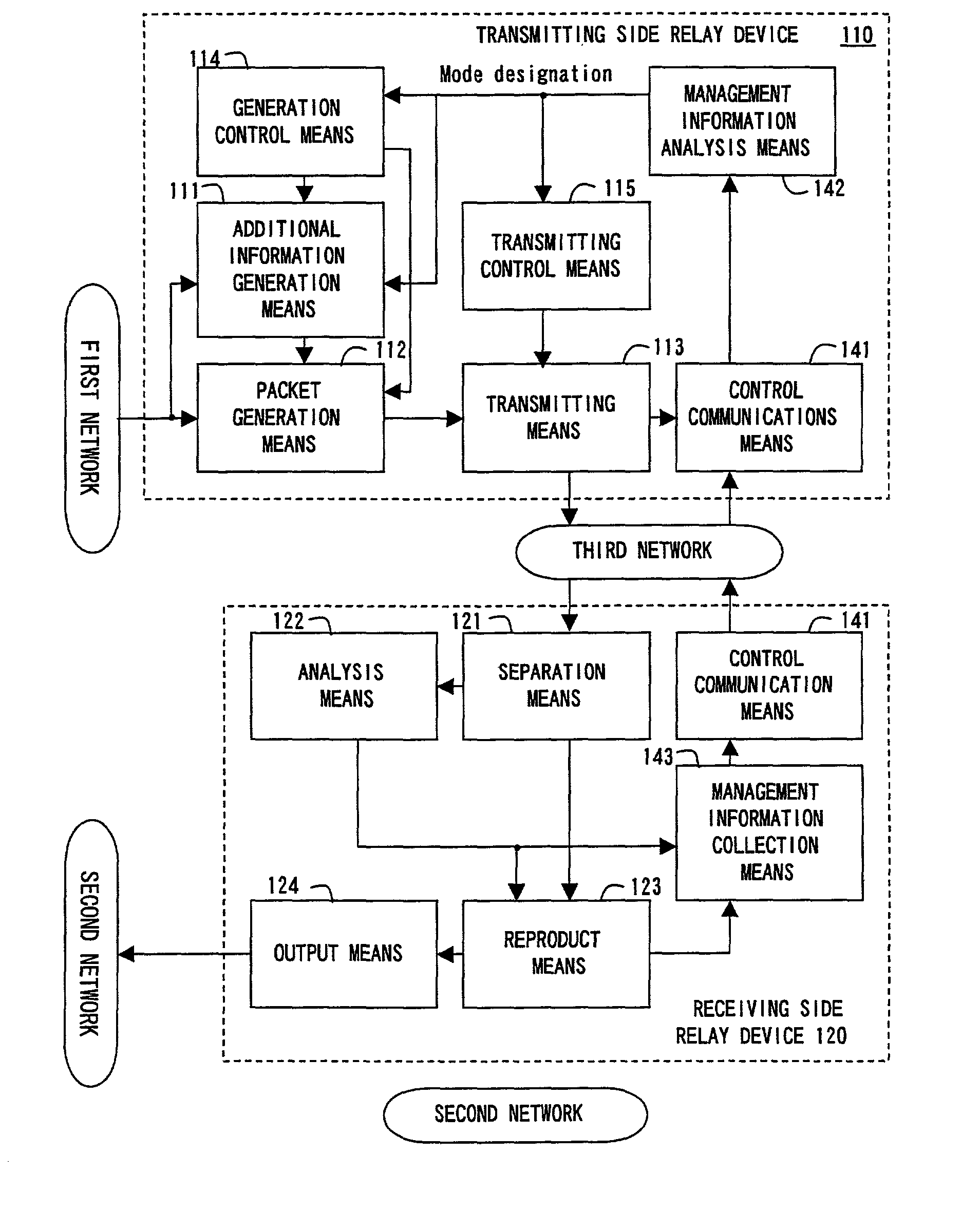
[0160]FIG. 7 shows the configuration of the data communications system.

[0161]According to the first preferred embodiment of the present invention, in a data communications system in which a transmitting side relay device 110 and a receiving side relay device 120 are connected to the first and second networks, respectively, for consecutively transferring prescribed transfer units at a specific transfer rate and with a specific transfer delay, and a data stream generated as a series of the transfer units are communicated as a series of datagram type packets, including the transfer unit via the third network, the transmitting side relay device 110 comprises additional information generation means 111 for generating additional information, including information about relationship between each transfer unit and the data stream based on the characteristics of the data stream, packet generation means 112 for generating a packet by attaching the additional information when each transfer uni...


PUM


Abstract

A transmitting side relay device comprises additional information generation means for generating additional information about the characteristics of a data stream, packet generation means for generating a packet by attaching additional information to each transfer unit and transmitting means for transmitting the packet to the third network according to prescribed procedures. A receiving side relay device comprises separation means for breaking down the received packet into additional information and a transfer unit, analysis means for analyzing the additional information, reproduction means for locating information included in a corresponding transfer unit in an appropriate position and reproducing the data stream and output means for outputting the data stream reproduced by the reproduction means to the second network.

Description

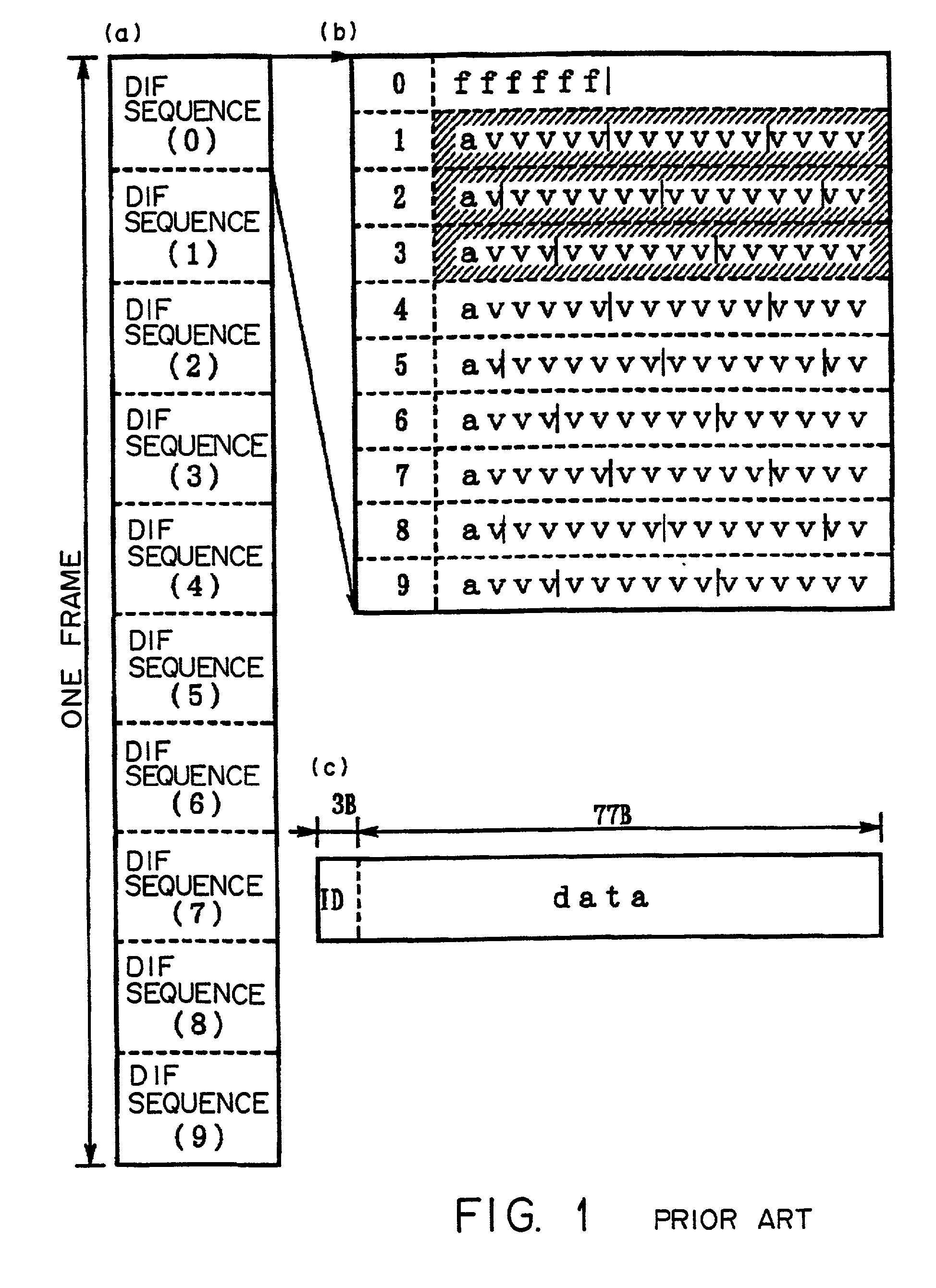
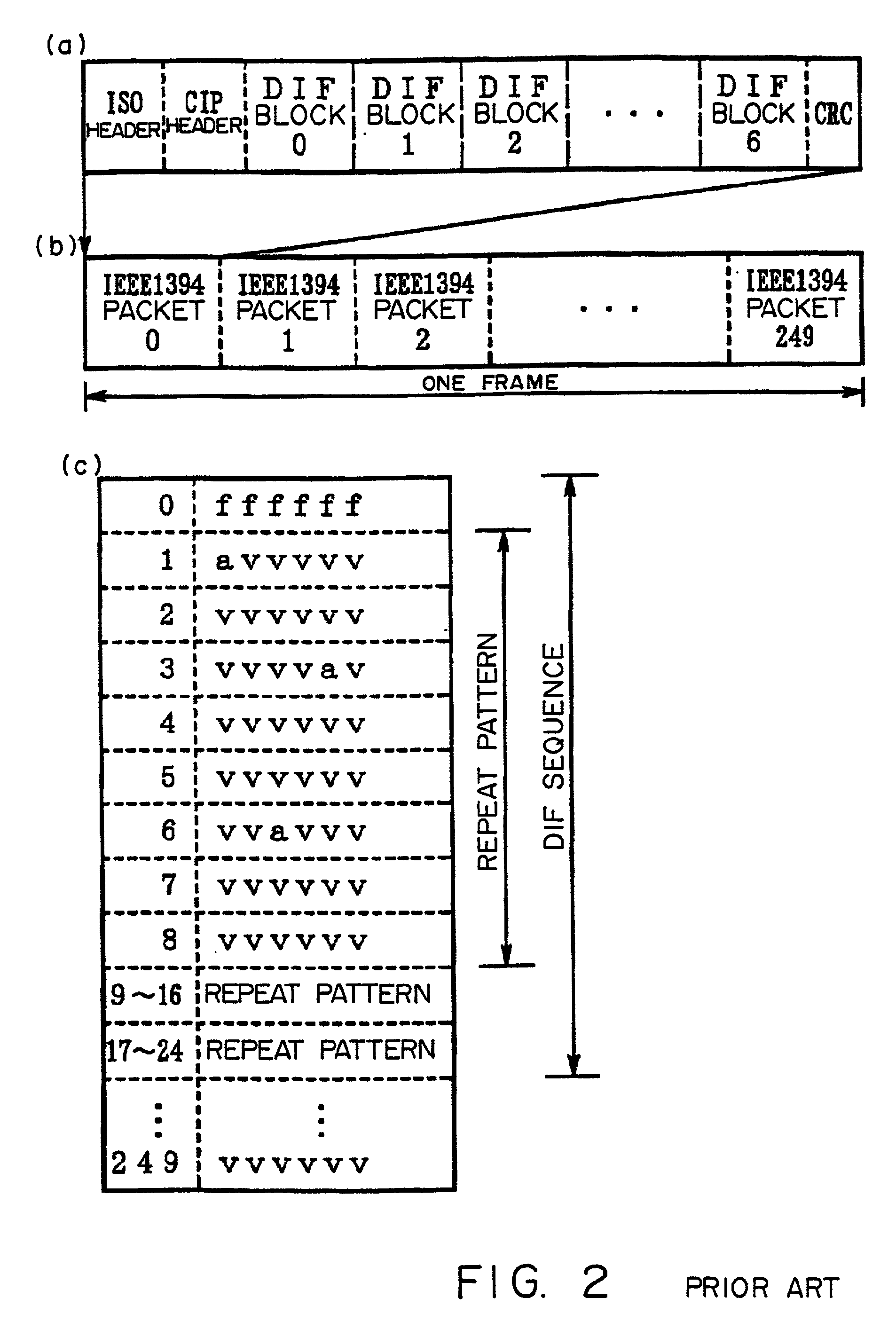
BACKGROUND OF THE INVENTION[0001]1. Field of the Invention[0002]The present invention relates to a data communications system for implementing a service for communicating data with a prescribed cyclical structure, such as animation data, etc., in high quality via a communications network adopting a datagram type communications protocol, such as the Internet, etc.[0003]As a standard for synchronously communicating animation data, such as digital video, etc., in a local bus, for example, IEEE1394 standard by IEEE (Institute of Electrical and Electronics Engineering) is used.[0004]Recently, with the spread of both equipment, such as a digital video camera, etc., and a high-performance personal computer to a general user, for example, a technology for connecting local networks configured according to the IEEE1394 standard to each other, for example, via the Internet and for relaying a data stream generated based on the standard of each local network is highly demanded.[0005]The present ...

Claims


Application Information

Patent Timeline
Patent Type & Authority Patents(United States)
IPC IPC(8): H04L12/28H04J3/24H04N7/04H04L12/40H04L12/64H04L29/06H04L29/08
CPCH04L12/40058H04L12/40071H04L12/40117H04L12/64H04L12/6418H04L29/06H04L65/607H04L69/16H04L69/166H04L69/164H04L69/168H04L29/06027H04L69/32H04L65/70H04L9/40H04L65/1101
Inventor JINZAKI, AKIRAKOGA, HISASHI
Owner FUJITSU LTD
Learn More