Spindle head for a universal milling machine

a milling machine and spindle head technology, applied in the direction of turning machine accessories, other manufacturing equipment/tools, manufacturing tools, etc., can solve the problems of limiting the free work space, affecting the quality of the finished product, and requiring considerable additional construction and cost-related expenses, so as to achieve the effect of reducing delays and large volum

Inactive Publication Date: 2006-11-14
DECKEL MAHO PFRONTEN GMBH
View PDF30 Cites 13 Cited by
  • Summary
  • Abstract
  • Description
  • Claims
  • Application Information

AI Technical Summary

Benefits of technology

[0008]It is the object of the invention to provide a spindle head for a universal milling machine enabling the complex machining of even bulky workpieces having a large volume in one setting with reduced delays.
[0010]The work area of the machine tool provided with the spindle head is considerably increased by the invention. The first work spindle incorporated in the spindle housing is designed for carrying out the different milling and drilling operations, and it is also dimensioned for roughing operations. Accordingly the normally required machining operations can each be carried out with a high machining performance using this work spindle. Roughing and coarser finishing operations are equally possible. The provision of a second spindle unit which is adjustable in two axes on the rear side of the spindle housing extends the work area of a machine tool since now fine finishing operations, engraving operations, fine drilling and the like can also be carried out in a simple manner and without a previous tool exchange. With the possibility to adjust the second work spindle in two axes perpendicular to each other inclined bores and grooves, undercuts as well as, with continuous angular adjustments, even spherical surfaces can be produced on the workpiece in a simple manner.
[0011]A further object of the invention is a machine tool provided with a spindle head designed as described above and a round table for accommodating large and bulky workpieces comprising an efficient rotational drive capable of rotating the workpiece with several 100 rpm. This additionally enables the execution of certain turning operations on the workpiece after the insertion of a turning tool, preferably into the first, more efficient work spindle. In addition, however, milling operations may as well be carried out on the rotating workpiece with the second spindle.
[0013]To obtain a high flexibility combined with a good stiffness the second spindle unit comprises a fork head rotatably mounted on the rear side of the spindle housing, a directly driven work spindle being pivotably supported between its fork. Conveniently said work spindle may be a high-speed spindle (HS spindle) with a rotation speed of more than 20,000 rpm.

Problems solved by technology

To this end, however, the different tools have to be inserted into and extracted from a single work spindle, which of course leads to a certain delays.
The console required for the exchange of the milling spindles limits the free work space and necessitates considerable additional construction- and cost-related expenses.

Method used


Image

  • Spindle head for a universal milling machine
  • Spindle head for a universal milling machine
  • Spindle head for a universal milling machine

Examples


Embodiment Construction

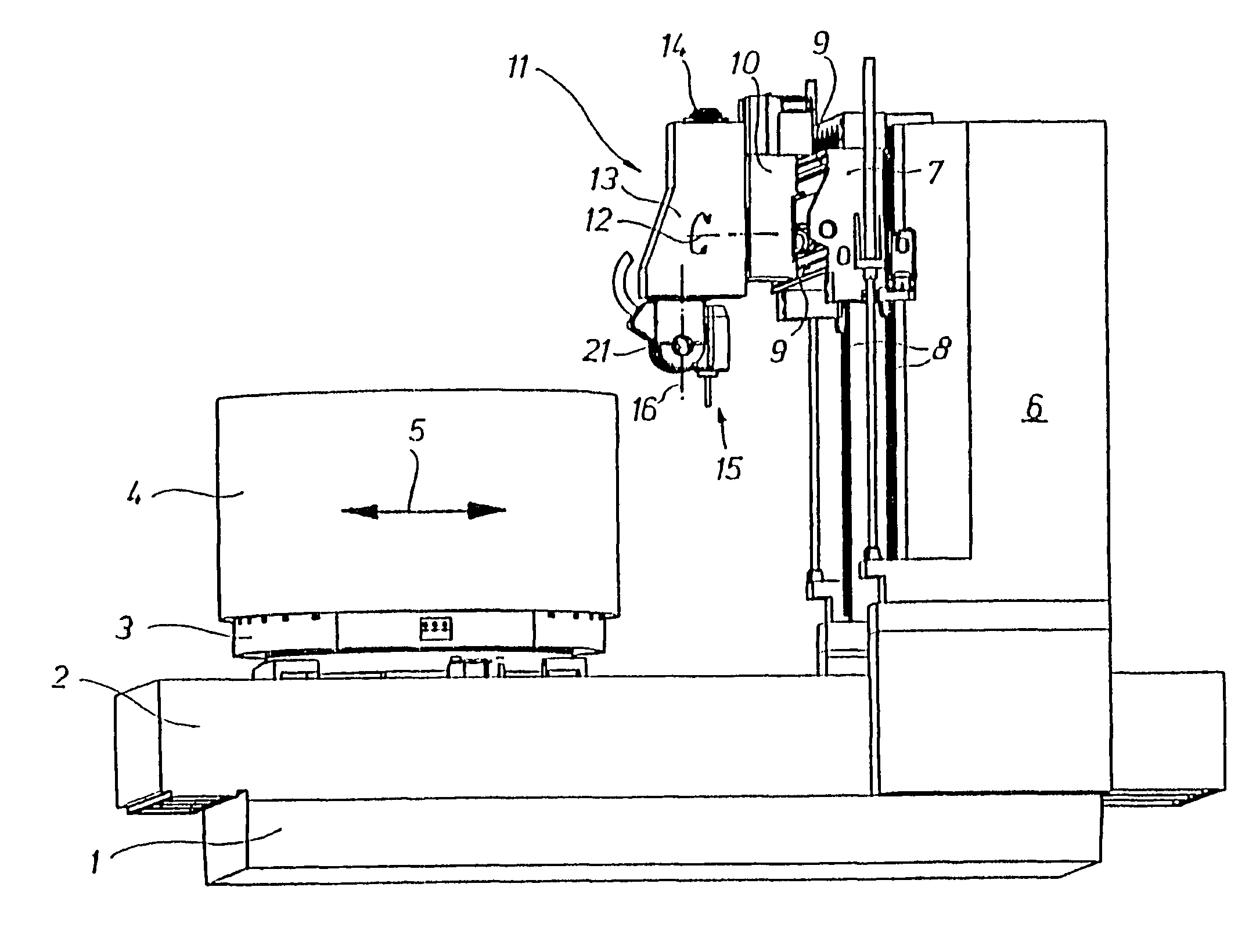
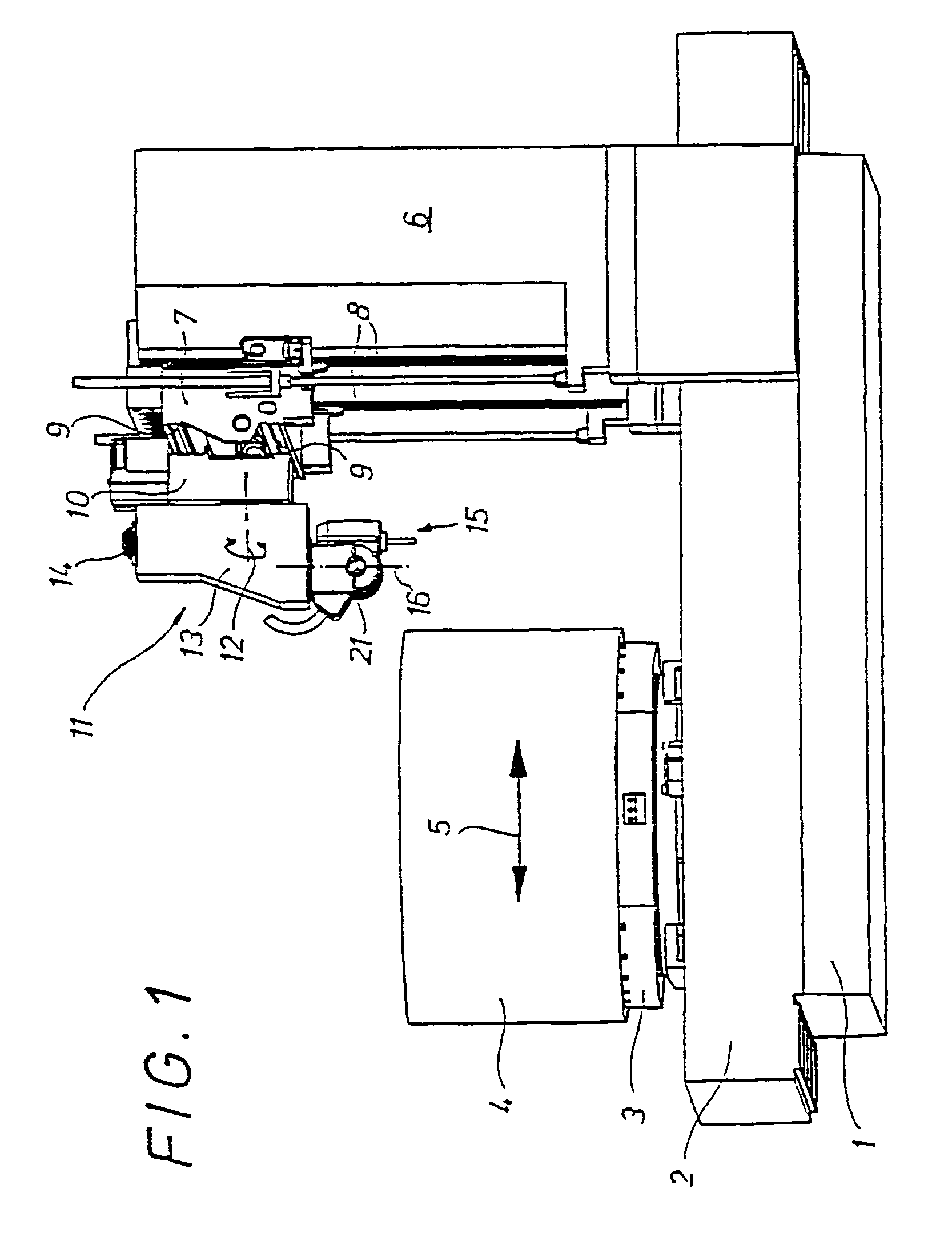
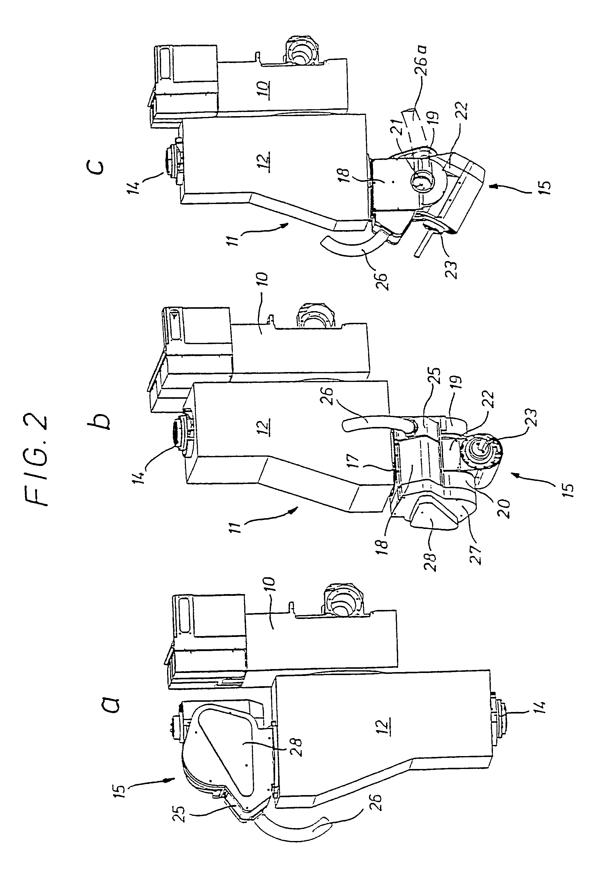
[0020]The universal milling machine shown in FIG. 1 comprises a continuous, highly rigid machine bed2 provided on a base 1, a round table 3 with a cylindrical workpiece 4 clamped thereon being disposed on said machine bed 2 so as to be shiftable in the direction of an arrow 5 by means of a motor. Further, a column 6 having a bridge structure is supported on the base 1, a slide 7 being disposed on the front side of the column 6 facing the workpiece 4 so as to be shiftable in vertical guides 8 by means of a motor. On horizontal front rails 9 of said vertical slide 7 a horizontal slide 10 is guided on the front side of which a spindle head 11 is fixed so as to be rotatable about a horizontal axis 12 by means of a motor. Said spindle head 11 comprises a housing 13 in which a first work spindle 14 is accommodated together with a direct driving motor. A first rotational drive for a fork head 15 is provided in the lower part of the spindle housing 13 which is widened according to FIG. 1, s...


PUM

PropertyMeasurementUnit
rotation axisaaaaaaaaaa
rotationaaaaaaaaaa
volumeaaaaaaaaaa

Abstract

A spindle head for a universal milling machine having a housing rotatably mounted on a machine part and a work spindle mounted axially parallel in the housing. A second spindle unit adjustable about two axes is disposed on the rear side of the housing.

Description

BACKROUND OF THE INVENTION[0001]1. Field of the Invention[0002]The invention relates to a spindle head for a universal milling machine of the type specified in the preamble of the claims as well as a universal milling machine provided with such a spindle head.[0003]2. Discussion of Related Art[0004]In recent times the complex machining of workpieces in one setting is aspired to increase product performance and accuracy. Various universal milling machines are already known in which even relatively large and bulky workpieces may be processed by milling and turning using rotatably driven round tables. Besides it has long been customary to carry out roughing and finishing works on a workpiece in the same machine. To this end, however, the different tools have to be inserted into and extracted from a single work spindle, which of course leads to a certain delays.[0005]Further, universal milling machines comprising two milling or spindle heads provided on a common console are known, for e...

Claims


Application Information

Patent Timeline
Patent Type & Authority Patents(United States)
IPC IPC(8): B23P23/00B23C1/14B23C1/12B23Q1/01B23Q1/50B23Q1/54B23Q1/62B23Q1/70B23Q5/04
CPCB23Q1/012B23Q1/5412B23Q1/623B23Q5/045B23Q2210/004Y10T409/305656Y10T409/307784Y10T409/404725Y10T29/5114Y10T409/307672B23Q2220/006
Inventor GSTIR, WALTERHAAS, PETER
Owner DECKEL MAHO PFRONTEN GMBH
Why Eureka
Try Eureka