Gas pressure regulator

a gas pressure regulator and gas pressure technology, applied in fluid pressure control, pressure relieving devices on sealing faces, instruments, etc., can solve the problems of increasing the number of regulators, complicating the installation of the regulator, increasing the manufacturing and installation costs of the gas supply system, etc., to reduce the number of leakage points, simplify the installation, and simplify the effect of mounting

Active Publication Date: 2006-11-14
VICTOR EQUIP
View PDF15 Cites 15 Cited by
  • Summary
  • Abstract
  • Description
  • Claims
  • Application Information

AI Technical Summary

Benefits of technology

[0005]Among the several objects of this invention may be noted the provision of a gas pressure regulator which can provide high gas flows at constant supply pressures; the provision of such a regulator which simpl

Problems solved by technology

The external piping required to accommodate the pilot regulator complicates the installation and increases both manufacturing and installations costs of the gas supply

Method used


Image

  • Gas pressure regulator
  • Gas pressure regulator
  • Gas pressure regulator

Examples


Embodiment Construction

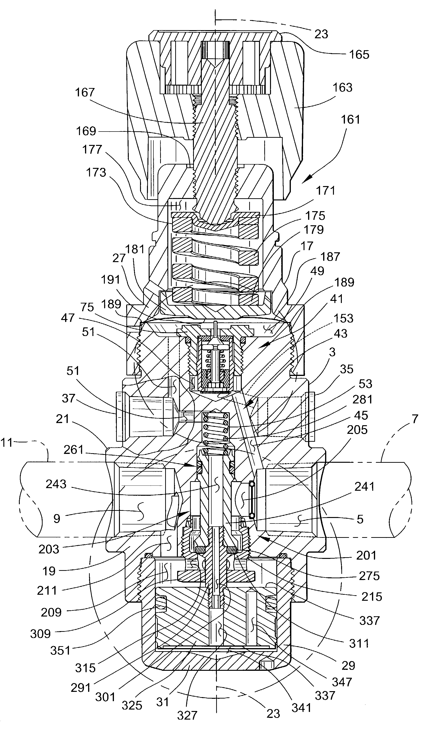
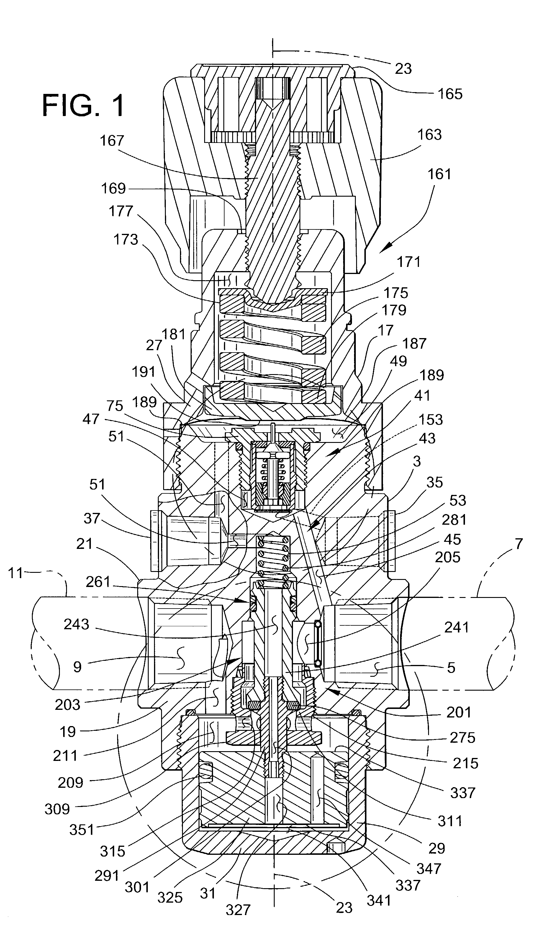
[0017]Referring now to the drawings, and more particularly to FIG. 1, a gas pressure regulator of the present invention is designated in its entirety by the reference numeral 1. The regulator 1 has a body 3 with an inlet 5 for connection to an upstream gas line 7 and an outlet 9 for connection to a downstream gas line 11. The regulator 1 supplies a flow of gas through the outlet 9 at a set pressure reduced from the gas pressure at the inlet 5 of the regulator.

[0018]In the illustrated embodiment, the regulator body 3 has a first end section 17, a second end section 19 and a central section 21 between the end sections that are generally coaxial with respect to a longitudinal axis 23 of the body. The first end section 17 comprises an upper cap or bonnet 27 and the second end section 19 comprises a cylinder head 29 having a bottom wall 31 defining a closed lower end of the regulator 1. In the preferred embodiment, both the bonnet 27 and the cylinder head 29 are threadably connected to t...


PUM


Abstract

A gas pressure regulator has an inlet for connection to an upstream gas line for flow of gas into the regulator under pressure and an outlet for connection to a downstream gas line for flow of gas out of the regulator at a reduced pressure. A pilot mechanism delivers a desired pilot gas pressure through a pilot passage. A main valve mechanism regulates the flow of gas through a main flow passage connecting the inlet and outlet of the regulator. The regulator has a piston chamber, and a piston operatively connected to the main valve mechanism and movable in the piston chamber. The main valve mechanism has a passageway between the piston chamber and the pilot passage whereby the pilot gas pressure is adapted to move the piston and thereby position the main valve mechanism to regulate the gas pressure at the outlet of the regulator.

Description

BACKGROUND OF THE INVENTION[0001]The present invention relates generally to a gas pressure regulator, and more particularly to a “dome loaded” pressure regulator having an internal pilot mechanism.[0002]One application for this invention is industrial laser applications where high gas flows are required at nearly constant pressures. One type of industrial laser application is laser cutting that typically uses a CO2 laser requiring a lasing gas that generates the laser beam and process, or assist gas, that is directed to the workpiece. Typical process gases include oxygen for cutting carbon steel and nitrogen for cutting stainless steel and alloys. Regardless of the gas used, all lasers require high process flows at an almost constant pressure to insure safe and efficient operation of the cutting apparatus. Typical laser cutting apparatus requires process gas flows as high as approximately 10,000 to 20,000 SCFH at delivery pressures up to approximately 500 PSIG.[0003]Preferred method...

Claims


Application Information

Patent Timeline
IPC IPC(8): G05D16/16F16K31/12
CPCG05D16/166Y10T137/7766Y10T137/7768Y10T137/777
Inventor BOYER, ROBERT A.
Owner VICTOR EQUIP
Why Eureka
Try Eureka